Pressure feedback
Tell us the working pressure and sensor signal used by the system. The drive can then be selected around the motor and feedback arrangement.
UFELE Electric — Solar Pumping, Industrial Drives and PV Protection
Email: sale@ufele.com | B2B Supply and OEM Orders

FU9000B is built for systems where demand changes during the day. Instead of running a pump or fan at one fixed speed, the drive can adjust motor speed around pressure, flow or other process feedback.
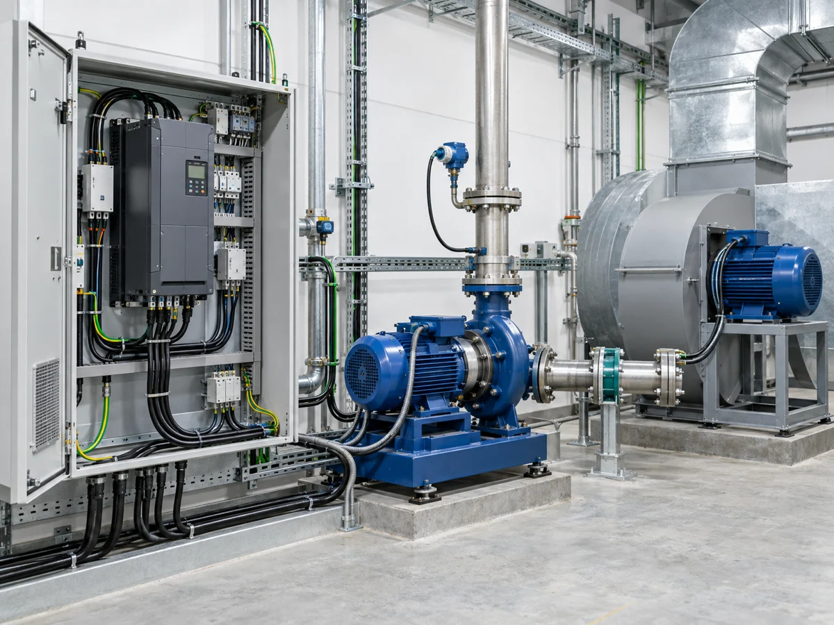
Water demand changes. Airflow demand changes. A process setpoint can also move. FU9000B is intended for those jobs, using feedback to adjust motor speed around the condition the system is trying to maintain.
That is a different selection problem from a conveyor or hoist. The motor plate still matters, but pressure, flow and the feedback device become part of the quotation data too.
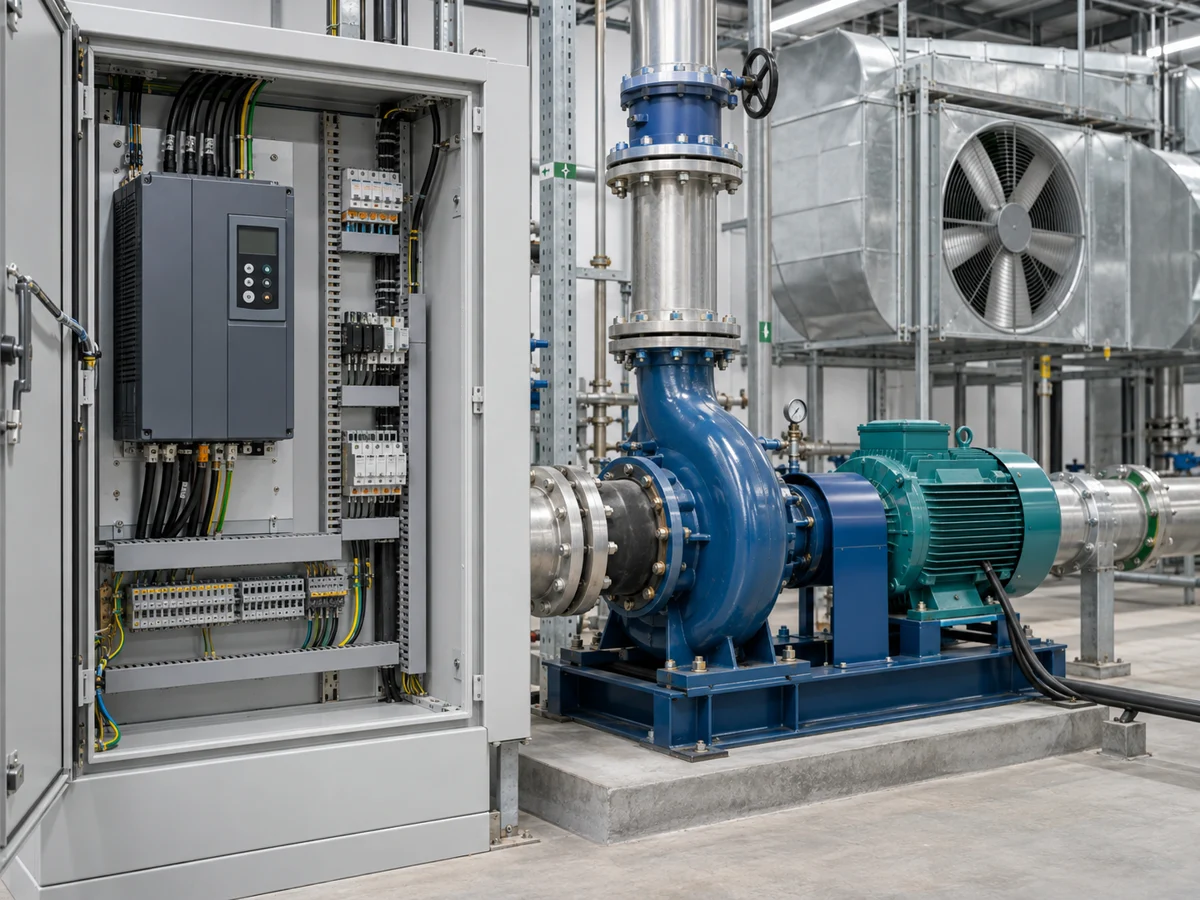
For many water systems it is pressure. For a ventilation system it may be airflow or another process condition. FU9000B is selected and set up around that feedback loop, not around motor speed by itself.
Tell us the working pressure and sensor signal used by the system. The drive can then be selected around the motor and feedback arrangement.
Where flow changes with demand, motor speed can be adjusted instead of treating the system as a simple full-speed on/off load.
FU9000B includes HVAC-specific functions for fan and building-service applications. The exact control logic depends on the system design.
FU9000B includes pipe rupture monitoring for pump applications. It gives the control system another way to watch for an abnormal operating condition instead of treating every pressure change as a normal demand change.
The threshold and response need to fit the actual hydraulic system. The pipe layout, sensor position and normal pressure range should be clear before the function is commissioned.

Pressure and flow demand are usually more useful than a generic ‘pump VFD’ description when choosing the drive.

Air systems often run under changing demand. The fan motor, control signal and airflow requirement should be reviewed together.

For distributor stock, separate the range by motor power and voltage class so common project sizes are easier to quote and replenish.
The drive sits between the electrical supply and the motor, while the process feedback tells the control loop what the system is doing. This simple view helps separate three different questions: is the motor sized correctly, is the feedback signal usable, and is the process setpoint realistic?
Pressure, flow or another process signal needs to reflect the condition the system is trying to control.
FU9000B adjusts motor operation according to the selected control strategy and feedback.
The pump or fan still has to be mechanically suitable for the required operating range.
| Project data | What it tells us |
|---|---|
| Motor nameplate | Power, current, voltage, frequency and motor speed. |
| Pump or fan type | Separates the electrical load from the process application. |
| Site voltage | Used to choose the correct 220, 380 or 480 V class. |
| Required pressure / flow | Defines the process target instead of choosing by motor size alone. |
| Feedback sensor | Shows how the actual process condition is sent back to the control system. |
| Normal operating pattern | Helps us understand whether demand is stable, intermittent or changing throughout the day. |
Pumps and fans are grouped together because both often run under variable demand, but the process data are not the same. A water system may be described by pressure and flow. An HVAC fan may be described by airflow, duct condition or a building-control signal. We keep the motor selection and the process selection separate until both are clear.
Send the pump motor plate, normal pressure, required pressure or flow, feedback sensor information and a short description of how demand changes. If pipe rupture monitoring is required, mention it at the quotation stage.
Send the fan motor plate, voltage, control signal and the operating condition the system is trying to maintain. If the drive will receive a command from a building or process controller, include that interface information too.
Process feedback only works when the sensor represents the condition the system actually needs to control. Sensor location, signal type and normal operating range should therefore be settled early. The drive can then be configured around a real process target instead of a guessed speed percentage.
For retrofit work, a photo of the existing sensor label and controller terminals can save time. It helps us see whether the new drive is expected to work directly with the sensor or receive a reference from another controller.
For a simple motor that only needs adjustable speed, a general-purpose VFD may be enough. FU9000B becomes more relevant when the project is built around a pump, fan or HVAC process and the motor speed needs to follow pressure, flow or another feedback signal.
This is why we ask about the process before choosing the series. The motor can be identical while the control requirement is completely different.
FU9000B orders are checked against the approved model and order file before shipment. Electrical and functional verification is part of the quality-control workflow. When a project depends on a specific feedback or protection function, that requirement should be clear in the order file.
FU9000B is UFELE’s pump and fan / HVAC VFD series. It is used where motor speed needs to follow changing system demand.
The series covers 1.5 to 500 kW (2–670 HP) with 220 V, 380 V and 480 V classes.
Yes. The series is intended for process-feedback control in pump and fan systems. The actual sensor signal and control arrangement should be specified during selection.
It is a pump-system function used to monitor abnormal operating conditions associated with a pipe problem. The exact setup should follow the FU9000B manual and the system design.
Send the motor nameplate, site voltage, pump or fan type, required pressure or flow condition, feedback sensor information and operating pattern.
That gives us both sides of the application: the motor and the process.