
Solar Pumping System for School and Community Water Supply in Kenya
A rural school and the surrounding community in Kenya needed a practical way to lift groundwater and keep water available beyond the hours of strongest sunlight. The completed installation combines 44 PV modules, a deep-well submersible pump, solar pump inverter control and two 10,000-liter storage tanks.
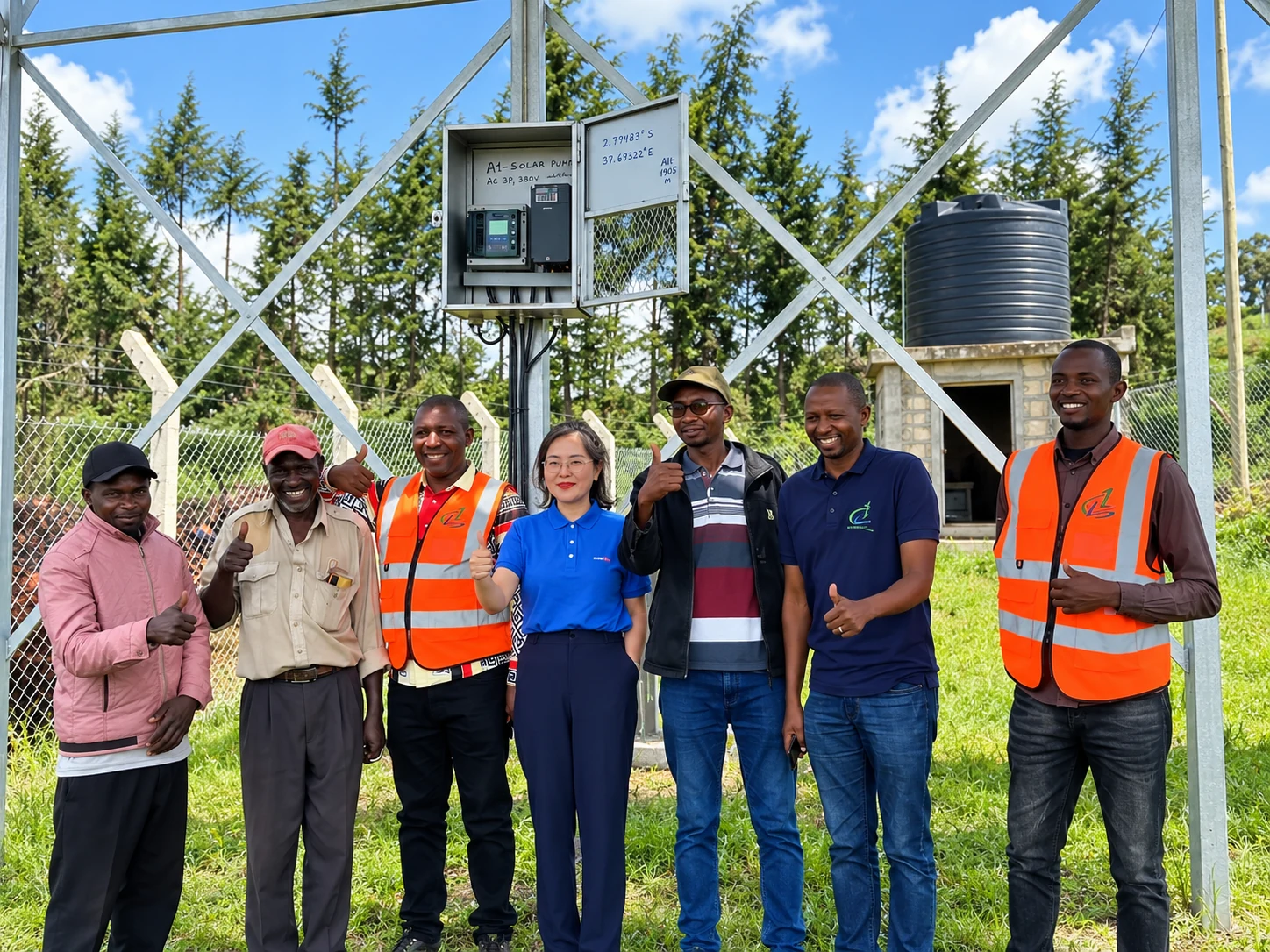
Project Configuration
The system combines a 44-module PV array, a deep-well submersible pump and two 10,000-liter water tanks to support daily water use for the school and nearby community.
| Item | Project Information |
|---|---|
| Country | Kenya |
| Application | School and community water supply |
| Water source | Groundwater / borehole |
| Pump type | Submersible pump |
| Pump installation depth | Approximately 150 m |
| Solar array | 44 PV modules |
| Solar pump inverter | Solar pump inverter for PV-powered water pumping |
| Water storage | 2 × 10,000 L tanks |
| Users | School and nearby community |
| Main purpose | Groundwater pumping and storage |
Lift Groundwater and Store It for Daily Use
The task was not simply to install an inverter. The system needed to lift groundwater from a deep source, move it to storage and make that stored water available to both the school and nearby community.
Deep Groundwater Source
The submersible pump was installed at approximately 150 m depth, making hydraulic conditions an important part of system selection.
Solar as the Primary Energy Source
The PV array supplies the energy required for pumping during available solar conditions.
Water Storage for Shared Use
Two 10,000 L tanks provide storage for both school and nearby community water use.
How the Installation Works
The installation follows a direct solar pumping architecture. The PV array supplies DC power to the solar pump inverter. The inverter controls the submersible pump, and pumped water is delivered to storage tanks for later use.
Installation Depth Is Not the Same as TDH
The submersible pump is installed at approximately 150 m depth. Pump installation depth and total dynamic head are different values, so hydraulic selection must also consider actual water level, elevation and pipe losses.
A complete hydraulic check for a similar project normally considers:
- Static water level
- Dynamic water level while pumping
- Vertical lift to the storage tank
- Pipe length and diameter
- Friction loss
- Required flow rate
- Required outlet pressure
Hydraulic Data for Similar Projects
For a comparable system, provide the static water level, dynamic water level, tank elevation, pipe length, pipe diameter and required flow. These values are used to calculate the actual pumping duty.
PV Array and Solar Pump Inverter Selection
The Kenya installation uses 44 solar panels. For a new system, module wattage, Voc, Vmp and the final series/parallel arrangement must be checked against the inverter DC input limits and the site temperature range.
1. Maximum String Voltage
Cold-weather string Voc must remain below the inverter’s maximum DC input voltage.
2. MPPT Operating Voltage
Array Vmp should remain inside the inverter’s usable MPPT operating range under expected site temperatures.
3. Available PV Power
Installed PV capacity should provide enough usable power for the pump under real solar conditions.
Why a Solar Pump Inverter Is Used
A PV array produces power that changes with sunlight, while the pump motor requires controlled electrical output. The solar pump inverter manages the interface between the two.
MPPT Control
Tracks available PV power so the drive can operate the pump more effectively as irradiance changes.
Motor Control
Converts DC input into controlled AC output and adjusts motor operation as available solar power changes.
Pump Protection
Current UFELE solar pump drives provide pump-oriented protection and water-level control functions when correctly configured.
Two 10,000 L Water Tanks
The installation uses two storage tanks, each with a nominal capacity of 10,000 liters, giving 20,000 liters of total nominal storage.
In a solar pumping system, tank storage can be more practical than storing large amounts of electrical energy. The pump operates when solar power is available, while the stored water remains available later.

Completed Water Supply Installation
The completed installation supplies water to both the school and the surrounding community. The system includes 44 PV modules, a deep-well submersible pump installed at approximately 150 m, solar pump inverter control and two 10,000 L storage tanks.

Kenya Installation Video
What to Check for a Similar Project
A similar installation should not be selected by copying the equipment rating from this project. Provide the actual hydraulic, motor and PV data for the new site.
| Required Data | Why It Matters |
|---|---|
| Pump rated power | Initial inverter sizing |
| Pump rated voltage | Determines inverter voltage class |
| Pump rated current | Confirms drive current capacity |
| Pump phase | Determines compatible output |
| Static water level | Hydraulic calculation |
| Dynamic water level | Actual pumping head |
| Required flow | Pump selection and daily water planning |
| Tank elevation | Adds vertical head |
| Pipe length and diameter | Friction-loss calculation |
| PV module Voc | Maximum string-voltage check |
| PV module Vmp | MPPT operating-voltage check |
| Module wattage | PV array sizing |
| Site temperature | PV voltage and inverter derating review |