
FU9000SI MPPT Solar Pump Inverter
FU9000SI converts PV power into controlled AC output for a water pump. MPPT follows the available solar power while the drive adjusts motor speed. Water-level inputs can stop the pump when the well is dry or the tank is full.
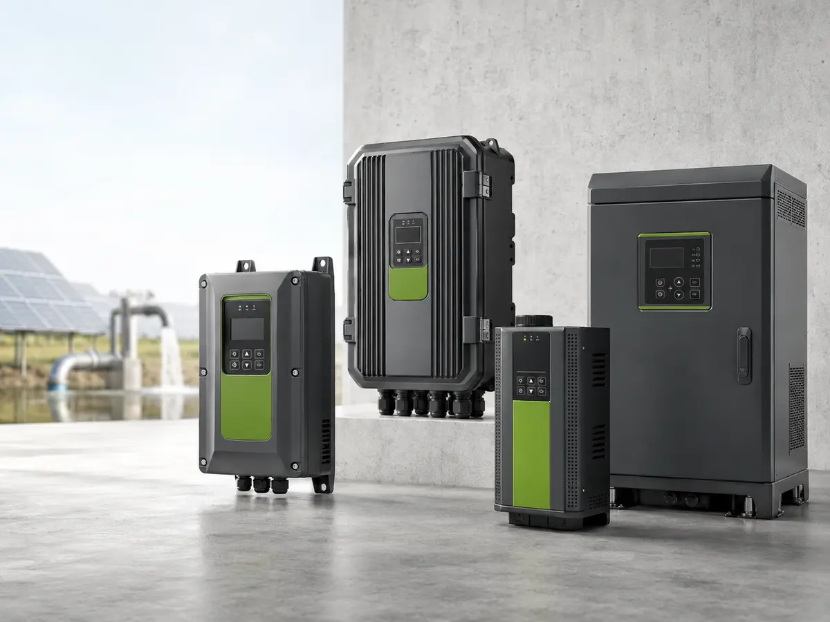
Series Overview
SS2
Single-phase 220-264 V AC input and single-phase 220-240 V pump output. The rated table lists 0.75-5.5 kW.
S2
Single-phase 220-264 V AC input and three-phase 220-240 V pump output. Confirm the active order code and rated current before purchase.
4 / 9
Three-phase 380-484 V AC input and three-phase 380-480 V pump output. The published -9 table covers 0.75-630 kW.
FU9000SI Rated Model Table
Choose the voltage class first. Then compare the pump nameplate current with the rated output current. Motor kW alone does not confirm the model.
| Model | Input | Output | Power (kW) | Rated input (A) | Rated output (A) | Pump type |
|---|---|---|---|---|---|---|
| FU9000SI-0R7G-SS2 | PV DC / 1PH 220-264 V | 1PH 220-240 V | 0.75 | 13.5 | 7.2 | Single-phase |
| FU9000SI-1R5G-SS2 | PV DC / 1PH 220-264 V | 1PH 220-240 V | 1.5 | 18 | 10.2 | Single-phase |
| FU9000SI-2R2G-SS2 | PV DC / 1PH 220-264 V | 1PH 220-240 V | 2.2 | 26 | 14 | Single-phase |
| FU9000SI-004G-SS2 | PV DC / 1PH 220-264 V | 1PH 220-240 V | 4 | 42 | 23 | Single-phase |
| FU9000SI-5R5G-SS2 | PV DC / 1PH 220-264 V | 1PH 220-240 V | 5.5 | 60 | 30 | Single-phase |
| FU9000SI-0R7G-9 | PV DC / 3PH 380-484 V | 3PH 380-480 V | .75 | 4.5 | 2.5 | Three-phase |
| FU9000SI-1R5G-9 | PV DC / 3PH 380-484 V | 3PH 380-480 V | 1.5 | 6.5 | 4.2 | Three-phase |
| FU9000SI-2R2G-9 | PV DC / 3PH 380-484 V | 3PH 380-480 V | 2.2 | 7.8 | 5.5 | Three-phase |
| FU9000SI-004G-9 | PV DC / 3PH 380-484 V | 3PH 380-480 V | 4 | 16 | 9.5 | Three-phase |
| FU9000SI-5R5G-9 | PV DC / 3PH 380-484 V | 3PH 380-480 V | 5.5 | 27 | 14 | Three-phase |
| FU9000SI-7R5G-9 | PV DC / 3PH 380-484 V | 3PH 380-480 V | 7.5 | 32 | 18.5 | Three-phase |
| FU9000SI-011G-9 | PV DC / 3PH 380-484 V | 3PH 380-480 V | 11 | 38 | 25 | Three-phase |
| FU9000SI-015G-9 | PV DC / 3PH 380-484 V | 3PH 380-480 V | 15 | 45 | 32 | Three-phase |
| FU9000SI-018G-9 | PV DC / 3PH 380-484 V | 3PH 380-480 V | 18.5 | 51 | 38 | Three-phase |
| FU9000SI-022G-9 | PV DC / 3PH 380-484 V | 3PH 380-480 V | 22 | 75 | 45 | Three-phase |
| FU9000SI-030G-9 | PV DC / 3PH 380-484 V | 3PH 380-480 V | 30 | 90 | 60 | Three-phase |
| FU9000SI-037G-9 | PV DC / 3PH 380-484 V | 3PH 380-480 V | 37 | 110 | 75 | Three-phase |
| FU9000SI-045G-9 | PV DC / 3PH 380-484 V | 3PH 380-480 V | 45 | 125 | 92 | Three-phase |
| FU9000SI-055G-9 | PV DC / 3PH 380-484 V | 3PH 380-480 V | 55 | 150 | 115 | Three-phase |
| FU9000SI-075G-9 | PV DC / 3PH 380-484 V | 3PH 380-480 V | 75 | 185 | 150 | Three-phase |
| FU9000SI-090G-9 | PV DC / 3PH 380-484 V | 3PH 380-480 V | 90 | 190 | 180 | Three-phase |
| FU9000SI-110G-9 | PV DC / 3PH 380-484 V | 3PH 380-480 V | 110 | 225 | 215 | Three-phase |
| FU9000SI-132G-9 | PV DC / 3PH 380-484 V | 3PH 380-480 V | 132 | 256 | 253 | Three-phase |
| FU9000SI-160G-9 | PV DC / 3PH 380-484 V | 3PH 380-480 V | 160 | 307 | 304 | Three-phase |
| FU9000SI-185G-9 | PV DC / 3PH 380-484 V | 3PH 380-480 V | 185 | 345 | 340 | Three-phase |
| FU9000SI-200G-9 | PV DC / 3PH 380-484 V | 3PH 380-480 V | 200 | 385 | 377 | Three-phase |
| FU9000SI-220G-9 | PV DC / 3PH 380-484 V | 3PH 380-480 V | 220 | 430 | 426 | Three-phase |
| FU9000SI-250G-9 | PV DC / 3PH 380-484 V | 3PH 380-480 V | 250 | 468 | 465 | Three-phase |
| FU9000SI-280G-9 | PV DC / 3PH 380-484 V | 3PH 380-480 V | 280 | 525 | 520 | Three-phase |
| FU9000SI-315G-9 | PV DC / 3PH 380-484 V | 3PH 380-480 V | 315 | 590 | 585 | Three-phase |
| FU9000SI-355G-9 | PV DC / 3PH 380-484 V | 3PH 380-480 V | 355 | 665 | 650 | Three-phase |
| FU9000SI-400G-9 | PV DC / 3PH 380-484 V | 3PH 380-480 V | 400 | 785 | 725 | Three-phase |
| FU9000SI-450G-9 | PV DC / 3PH 380-484 V | 3PH 380-480 V | 450 | 883 | 820 | Three-phase |
| FU9000SI-500G-9 | PV DC / 3PH 380-484 V | 3PH 380-480 V | 500 | 920 | 860 | Three-phase |
| FU9000SI-630G-9 | PV DC / 3PH 380-484 V | 3PH 380-480 V | 630 | 1210 | 1200 | Three-phase |
PV Input Parameters
| Parameter | 220 V class | 380 V class |
|---|---|---|
| Applicable suffix | SS2 / S2 | 4 / 9 |
| Maximum DC input voltage | 450 V | 800 V |
| Recommended MPP voltage | 330 V | 550 V |
| Start voltage | 200 V | 300 V |
| Minimum operating voltage | 150 V | 250 V |
| Recommended PV input range | 200-450 V DC | 300-750 V DC |
PV and AC Input Logic
PV input
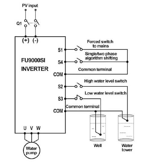
Connect the array through DC breaker Q1 to the positive and negative PV terminals. Parallel strings require a PV combiner box.
AC backup
Connect mains power through an external interlocked contactor circuit. The drive relay controls the contactor coil. The drive does not contain a built-in ATS.
Input priority
P15.32 selects automatic, forced mains or forced PV operation. The factory setting is forced PV.
| Setting or condition | Response | Published value |
|---|---|---|
| P15.32 = 0 | Automatic PV/mains selection through the external switching circuit | Automatic |
| P15.32 = 1 | Use mains input | Forced mains |
| P15.32 = 2 | Use PV input | Forced PV; factory setting |
| PV falls below the switch threshold or weak-light state | Relay can transfer the external contactor to mains | P15.33 default 70 V |
| PV rises above the recovery threshold | Relay can return the external contactor to PV after the wake delay | P15.34 default 100 V; P15.24 default 300 s |
| Forced-mains digital input is active | The terminal command overrides P15.32 | S1 / function 42 |
Protection and Pump Alarms
| Protection | Code | What it monitors | Drive response |
|---|---|---|---|
| Dry source / underload | A-LL / LL | Pump current and load condition | Alarm or stop after the set delay; restart follows the configured recovery delay |
| Tank full | A-tF | High-water switch at S2 | Stops after the set delay and waits for the level condition to clear |
| Source empty | A-tL | Low-water switch at S3 | Stops after the set delay and waits for water recovery |
| Level probe fault | tSF | Hydraulic probe circuit | Reports the fault and stops when probe-fault protection is enabled |
| PV reverse polarity | PINV | PV input polarity | Blocks normal operation; correct the PV polarity |
| PV overcurrent | PVOC | PV/boost input current | Trips and requires array, load and wiring checks |
| PV overvoltage | PVOV | PV input voltage | Trips; reduce the number of modules in series |
| PV undervoltage | PVLV | PV input voltage and available array power | Stops or waits for sufficient solar input |
| Weak light | A-LS | Available PV power | Sleeps and starts again when sunlight recovers |
| Motor overcurrent | OC1 / OC2 / OC3 | Motor output during acceleration, deceleration or steady speed | Current limiting or trip according to the fault condition |
| DC bus overvoltage | OV1 / OV2 / OV3 | DC bus during acceleration, deceleration or steady speed | Trips and records the operating stage |
| DC bus undervoltage | UV | DC bus voltage | Stops until the supply condition is corrected |
| Motor / drive overload | OL1 / OL2 | Motor and inverter thermal load | Trips to prevent sustained overload |
Control Terminals
| Terminal | Function | Signal or rating | Typical connection |
|---|---|---|---|
| +24V / COM | Auxiliary supply and common | 24 V DC ±10%, 200 mA maximum | Digital inputs or compatible sensors |
| S1 / COM | Forced switch to mains | 12-24 V digital input; 3.3 kΩ | External selector or transfer command |
| S2 / COM | Tank-full input | Normally open by default | High-water level switch |
| S3 / COM | Source-empty input | Normally closed by default | Low-water level switch |
| S4 / COM | Single-/two-phase algorithm selection | High level selects single-phase | Pump phase algorithm command |
| AI1 | Keypad potentiometer input | Analog reference | Local analog setting |
| AI2 | Analog input | 0-10 V or 0-20 mA by jumper | Compatible level or process transmitter |
| AI3 | Analog input | -10 to +10 V | Compatible bipolar analog signal |
| RO1A / RO1B / RO1C | Relay NO / NC / common | 3 A at 250 V AC; 1 A at 30 V DC | Alarm or AC contactor-coil control |
| RS485+ / RS485- | Modbus RTU | Two-wire RS485 | PLC, gateway or optional remote module |
| 422 TX / RX | Boost-module communication | Dedicated communication link | Matching boost module |
Wiring
PV to pump
PV array → DC breaker Q1 → FU9000SI (+/-) → U/V/W → pump
PV with AC backup
PV array + mains supply → external interlocked contactor circuit → FU9000SI → pump
Level switches
Tank high-level switch → S2/COM. Well low-level switch → S3/COM.
Dimensions and Weight
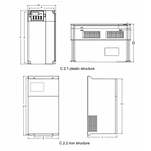
| Model group | A × B mounting (mm) | H × W × D (mm) | Hole | Weight |
|---|---|---|---|---|
| SS2 0R7-5R5 | 152 × 305 | 320 × 170 × 200 | 5.5 mm | 6.75 kg |
| -9 0R7-018 | 152 × 305 | 320 × 170 × 200 | 5.5 mm | 6.75 kg |
| -9 022-075 | 175 × 540 | 560 × 290 × 285 | 8 mm | 32 kg |
| -9 090-160 | 250 × 730 | 750 × 400 × 340 | 10 mm | 62 kg |
| -9 185-400 | 650 × 869 | 1470 × 960 × 470 | 12 mm | 175 kg |
| -9 450-630 | 1658 × 440 | 1860 × 720 × 650 | 16 mm | 333 kg |
Installation Conditions
Temperature
Operate from -10°C to +50°C. Above 40°C, reduce output by 2% for each 1°C rise.
Cooling
Keep the cooling path open. Allow space for air movement and keep the drive away from direct solar heat.
External protection
Size DC isolation, fuses, surge protection, AC breakers, contactors, cables and grounding for the final circuit.
Documents
FU9000SI User Manual
Rated data, parameters, terminals, fault codes and installation details.
Certificate and Wiring Diagram
Request documents that match the ordered model and destination market.
FU9000SI FAQ
Can FU9000SI run a single-phase pump?
Yes, with an SS2 configuration and the correct pump wiring. S2 is used for single-phase input with three-phase output. Confirm the motor voltage, phase, current and capacitor arrangement before selection.
Does FU9000SI switch between PV and mains automatically?
Automatic selection is available through the drive relay and a correctly wired external interlocked contactor circuit. It is not a built-in ATS.
Is the FU9000SI IP65?
This product specification states IP20 for indoor, conditioned installation. An outdoor enclosure or a separately documented IP65 model is required for exposed sites.
How should I choose the PV string?
Check cold-weather Voc against the maximum input voltage. Check hot-weather Vmp against the operating range. Then size array power from pump duty and the local solar resource.
What information is needed for a quotation?
Send the pump nameplate, voltage, phase, rated current, head, flow, location, panel datasheet, cable length, water-level controls and required AC backup method.
Confirm the FU9000SI Configuration
Send the pump nameplate and PV module datasheet. We will check the voltage class, output current, PV string, frame size and switching circuit.