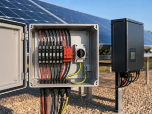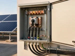
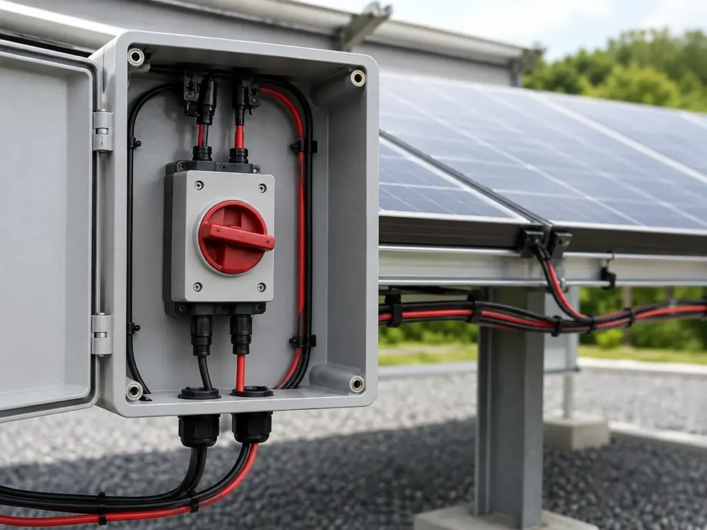
A DC isolator has a modest job on the drawing: give someone a visible way to separate a live PV circuit. The difficulty appears when a familiar-looking switch is expected to interrupt the wrong voltage, current, or wiring arrangement. That is where a small purchasing decision can leave an installer with a serious problem.
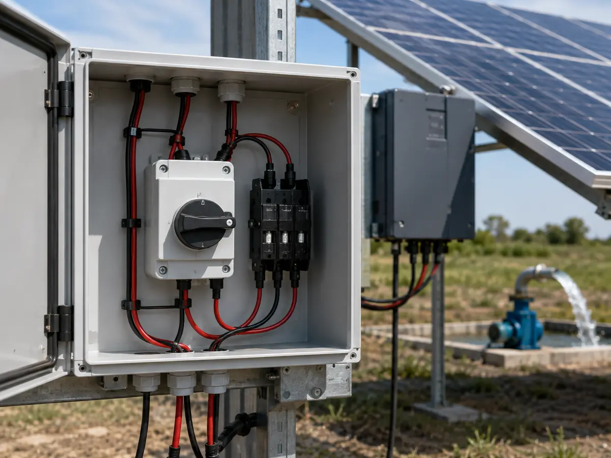
How do you choose a DC isolator switch?
Start with the circuit it must disconnect, not the current printed in large type on the front. Record the maximum PV voltage after cold correction, the design current, the number of poles used in the approved wiring diagram, and whether the switch must break current under load. Then check the DC utilization category, enclosure, operating temperature, terminals, mounting method, and the certificate for the exact model. If the rating depends on a particular pole arrangement, that drawing becomes part of the selection.
A quotation may say “1,000 V DC, 32 A isolator” and look complete. I would still hesitate. Those two numbers do not reveal whether the device reaches that rating with two poles, four poles, or a linked series arrangement. They also say nothing about the current the switch can actually make and break on a PV circuit.
This matters because a PV array keeps producing whenever light reaches it. Direct current does not pass through a natural zero point on every cycle as alternating current does. An unsuitable contact arrangement may struggle to extinguish the arc when it opens. The handle can reach OFF while the electrical stress inside the switch tells a less reassuring story.
In a multi-string installation, isolation often sits beside overcurrent and surge protection. A PV combiner box may bring those functions into one enclosure, but each device still needs its own verified rating and coordination. An isolator provides isolation; it should not be quietly treated as a fuse, circuit breaker, or surge protective device.
Begin with the circuit, not a catalogue photograph
The first useful document is a single-line diagram. It should show the array strings, positive and negative conductors, earthing arrangement, combiner, inverter inputs, and every proposed isolation point. Without that drawing, the same product name can refer to quite different duties.
Next, bring in the module sheet and the array calculation. The isolator must withstand the highest voltage the circuit can produce, which commonly means corrected open-circuit voltage on the coldest credible morning. It must also carry the relevant design current without unacceptable heating. Local rules, the equipment instructions, and the designer’s chosen safety factors still govern the final values.
| Project record | What to confirm | Why we stop when it is missing |
|---|---|---|
| PV array calculation | Cold-corrected maximum voltage, Imp, Isc, parallel strings, and design current | The isolator cannot be approved from array power alone |
| Single-line diagram | Polarity, earthed or unearthed conductors, isolation points, and pole arrangement | The claimed voltage rating may depend on the exact series connection |
| Installation plan | Indoor or outdoor position, ambient temperature, sun, moisture, dust, altitude, and enclosure | Heat and contamination can change what survives in service |
| Exact product file | Model code, data sheet, wiring diagram, standard, certificate, and terminal range | A family brochure does not prove the rating of the ordered variant |
Check the DC switching duty, not just the word “isolator”
A switch-disconnector intended for PV use should state the applicable standard and utilization category. IEC 60947-3 includes categories used for switching DC circuits, while PV applications commonly refer to DC-PV2 for switching a PV circuit where substantial overcurrents may occur. Do not infer that marking from the enclosure colour or the shape of the rotary handle.
The uncomfortable question is simple: may this device open the circuit while current is flowing, or is it intended only for off-load isolation after another device has interrupted the current? The answer affects work procedures and the product itself. If the supplier cannot point to the rating table and operating category, the schedule is not ready for approval.
Match the voltage rating to the approved pole arrangement
The array’s STC voltage is not the number to use blindly. Cold weather increases module Voc, so the series count and temperature coefficient must be applied before the isolator voltage is checked. A device placed on a 1,000 V-class system should not be approved merely because “1,000 V” appears somewhere in a product family table.
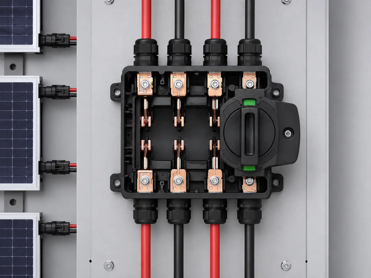
Many compact PV isolators use multiple contacts in series to interrupt higher DC voltage. That makes the wiring diagram part of the rating. Reversing a link, using fewer poles, or routing only one conductor through an arrangement designed for both polarities can invalidate the expected performance. The installer deserves a diagram that matches the terminal numbers on the supplied switch.
Whether both positive and negative conductors must be switched depends on the system topology and applicable rules. Do not copy a two-pole or four-pole arrangement from a different earthing system. Confirm the inverter design, local standard, and isolation requirements first.
Treat current as a thermal and switching question
The current marked on a device deserves context. We compare the project design current with the isolator’s operational current at the relevant DC voltage, utilization category, pole arrangement, and ambient temperature. A generous-looking 32 A front label may no longer feel generous inside a sun-warmed box.
Parallel strings raise the current reaching a common isolator. Isc, the required multiplier, and any reverse-current condition should be considered under the project’s design rules. The terminal must also accept the specified conductor without cutting strands, leaving copper exposed, or relying on a ferrule the manufacturer does not permit.
Heat often exposes a weak selection before anything else does. Loose terminations, undersized conductors, high ambient temperature, poor ventilation, and repeated operation can all raise contact temperature. Ask for tightening torque, stripping length, conductor range, and any derating data. These details are less attractive than a product photo, but they are the details an electrician needs at the cabinet.
Choose the enclosure for the place it must endure
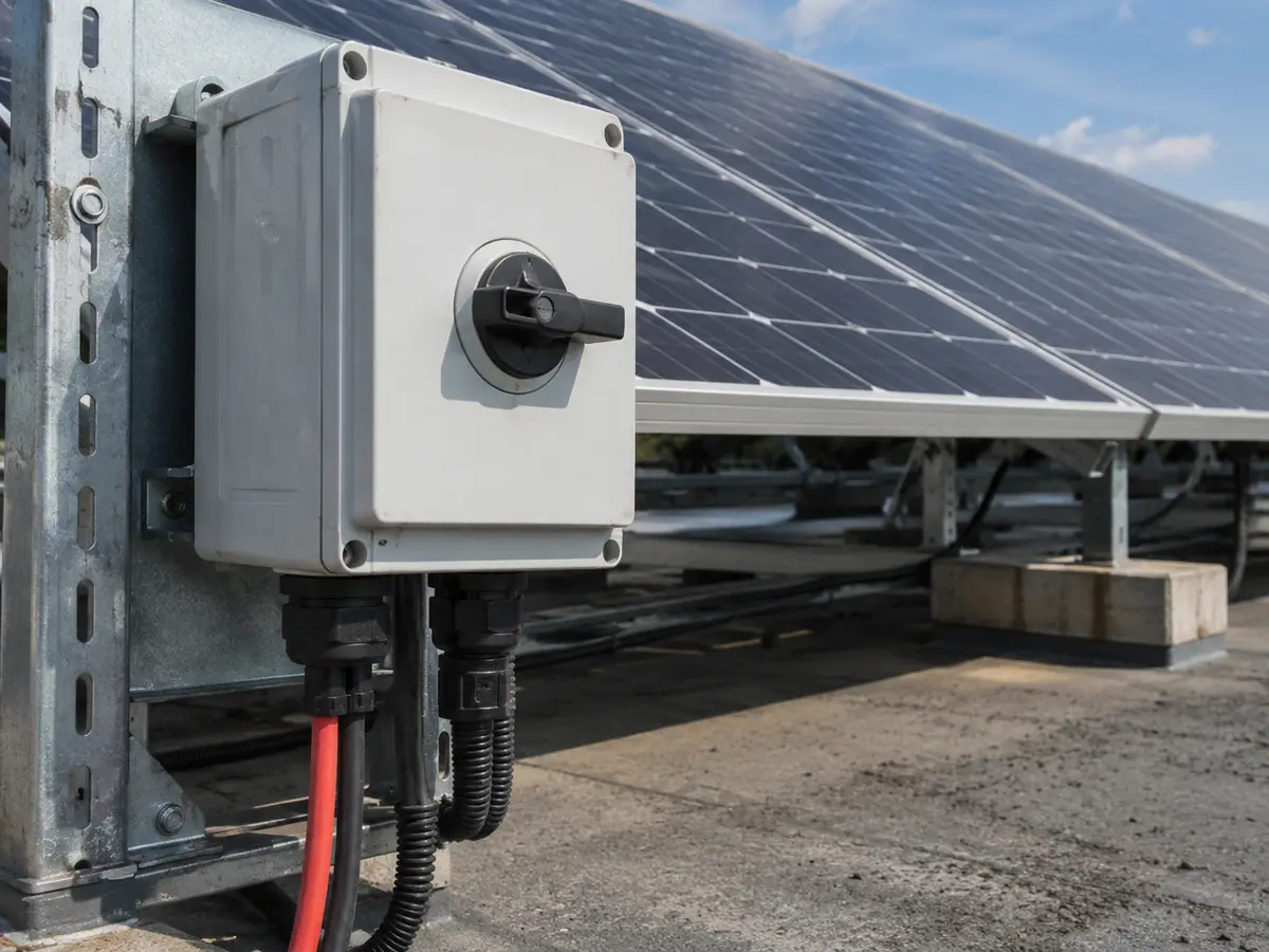
An indoor isolator inside a suitable distribution board faces a different life from a rooftop unit mounted under direct sun. For outdoor use, verify the complete enclosed assembly’s IP rating, UV resistance, cable-gland arrangement, drainage, condensation control, mounting orientation, and operating-temperature range. The switch mechanism alone does not give the finished installation its enclosure rating.
Outdoor plastic can become brittle, seals can be disturbed by the wrong gland, and a badly placed cable entry can guide water toward the terminals. I would rather see a plain installation drawing now than an impressive enclosure photographed before anyone drilled it. Once holes are added at site, their position and sealing matter.
Accessibility also needs thought. The handle should be reachable for maintenance without putting the operator in another hazard. Labels must remain legible, the OFF position should be clear, and lockout provisions should suit the maintenance procedure. A hidden switch may look tidy; it is not useful when someone needs to isolate the circuit quickly.
Read the certificate beside the model code
A certificate logo on a sales page is only a prompt to ask for the document. Check the manufacturer, product family, exact model or covered series, ratings, standard, issuing body, issue status, and any limitations. If the ordered enclosure includes a separate switch mechanism, confirm what the certificate actually covers.
IEC 60947-3 is a useful reference point for switches, disconnectors, switch-disconnectors, and fuse-combination units. Yet naming a standard does not prove compliance. Keep the declaration, certificate where applicable, test evidence requested by the destination market, and matching product label with the order file.
Photographs can confirm markings, terminal layout, and obvious construction details. They cannot replace interruption tests or temperature-rise evidence. When a project requires third-party approval, agree on the required document set before production. Discovering a model-scope problem after labels and cartons are finished is frustrating for everyone.
Illustrative review: a 1,000 V DC, two-string circuit
Imagine a proposed circuit with two parallel PV strings. The design file gives a cold-corrected maximum voltage of 924 V, one-string Isc of 13.9 A, and a project design current of 34.8 A after the applicable multiplier. The buyer is offered a four-pole isolator described as 1,000 V DC and 40 A.
Nothing in that sentence approves the switch. We still need to see whether 1,000 V and 40 A appear together at the required utilization category, whether the four-pole series arrangement matches the drawing, and whether the 40 A rating remains valid at the enclosure temperature. Terminal capacity and certification scope come next.
| Review point | Illustrative project value | Evidence still needed |
|---|---|---|
| Maximum circuit voltage | 924 V after cold correction | 1,000 V DC operational rating for the exact pole arrangement and category |
| Design current | 34.8 A | Operational current above this value at the relevant voltage and enclosure temperature |
| Conductors | Positive and negative to be isolated | Approved four-pole wiring diagram for the project topology |
| Location | Outdoor enclosure in direct sun | Assembly IP/UV rating, temperature data, glands, and mounting instructions |
| Compliance | Destination documents specified by buyer | Current certificate and label matching the ordered model |
This example is deliberately close enough to make us uneasy. A 40 A claim over a 34.8 A design current leaves little room for a temperature derating that has not yet been checked. The right response is not to approve it optimistically. It is to obtain the manufacturer’s rating table or select a configuration with verified margin.
Mistakes that usually begin with an incomplete product line
The first is choosing by “DC voltage” without checking the number of poles used to earn that rating. The second is treating an AC isolator with a similar current rating as an acceptable substitute. Contact spacing, arc control, switching categories, and certified ratings are not transferred by appearance.
Another common mistake is putting every DC device under the broad word “breaker.” An isolator, fuse, circuit breaker, and SPD answer different hazards. If the bill of materials blurs those functions, pause before ordering. Clear naming helps the installer wire the system and helps the buyer compare quotations fairly.
Finally, avoid approving from a family certificate or a label mock-up alone. Model suffixes may identify current ratings, pole counts, handles, enclosures, or terminal options. One missing suffix can be the difference between the item reviewed and the item packed.
What to send for a reliable quotation
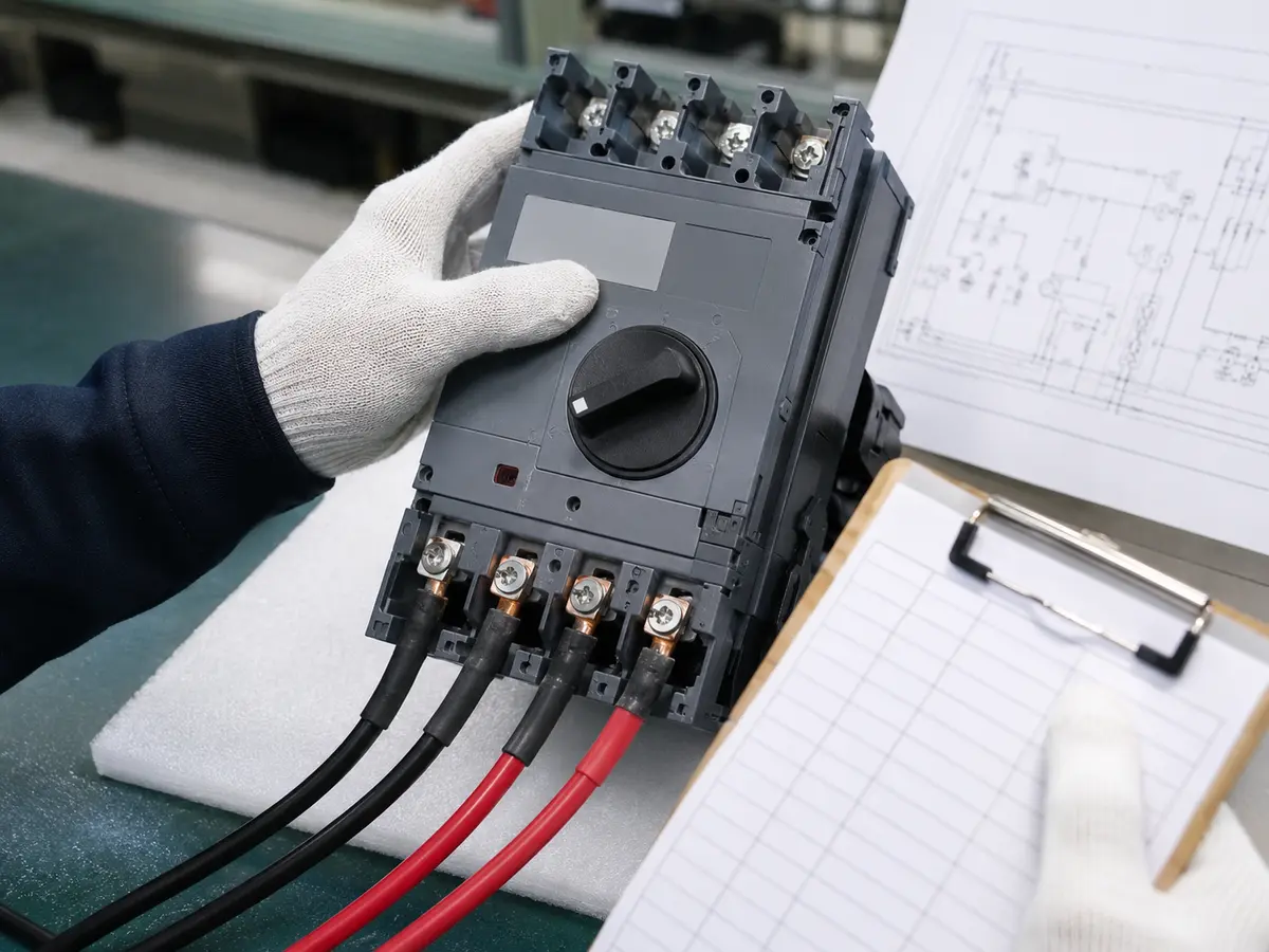
Send the single-line diagram, module data sheet, string count, modules per string, cold-corrected maximum voltage, design current, system earthing arrangement, inverter model, cable size, and installation location. Add the destination market and document requirements. If an enclosure is required, describe the mounting, cable entries, expected temperature, sun, rain, dust, and corrosion exposure.
DC isolator approval checklist
- Exact model and full suffix are recorded
- Cold-corrected PV voltage is below the verified operational rating
- Design current suits the stated DC category, voltage, and temperature
- Pole count and terminal links follow the approved wiring diagram
- Load-switching duty and isolation procedure are understood
- Conductor range, stripping length, and terminal torque are documented
- The complete enclosure suits the installation environment
- Certificates and product labels cover the ordered model
UFELE supplies solar DC isolation and related solar energy equipment for distribution and project orders. You can also review our electrical product certificates and compliance information. Send the project file through the contact page; we will identify missing selection details before placing a model on the quotation.
Frequently asked questions
What rating should a DC isolator have for a solar PV system?
Its DC voltage and current ratings must be suitable for the maximum PV string voltage and operating current under the project conditions. Always check the device datasheet and applicable system design limits.
Can an AC isolator be used on a DC solar circuit?
Do not assume an AC-rated isolator is suitable for PV DC switching. Use a device with a DC rating that matches the system voltage, current and switching category.
Why do some 1,000 V DC isolators use four poles?
Series pole arrangements can be used to increase DC breaking capability at higher voltages. The correct wiring arrangement must follow the manufacturer’s approved diagram.
Does a DC isolator protect against overcurrent?
No. An isolator provides switching and isolation; overcurrent and surge protection are separate functions and must be selected according to the system design.
Should both positive and negative PV conductors be isolated?
This depends on the system earthing arrangement, inverter design and applicable local rules. Follow the approved system design and the isolator manufacturer’s wiring instructions.
What documents should I request from a DC isolator supplier?
Request the exact data sheet, DC rating table, approved wiring diagram, installation instructions, applicable certificate or declaration, terminal details, label artwork, and environmental ratings for the ordered model.