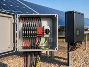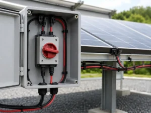
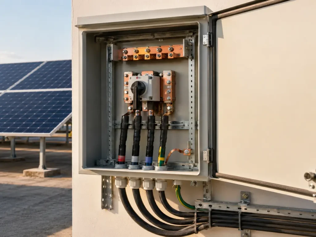
A request for a “10-in, 1-out, 1,000 V box” looks ready for quotation. It rarely is. We still need to know what each string can deliver, how high its voltage rises on the coldest morning, what current can return through a faulted string, and how hot the enclosure becomes in service. PV combiner box sizing starts with those project conditions. The number on the enclosure label comes later.
How do you size a PV combiner box?
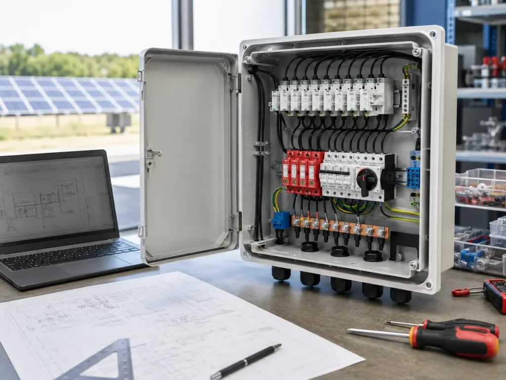
Confirm the number of strings, modules per string, cold-corrected maximum open-circuit voltage, string short-circuit current, module maximum series-fuse rating, inverter input limits, cable capacity, earthing arrangement, and site conditions. Use those values to review string protection, SPD voltage and protection mode, DC isolator poles and current, busbars, output protection, terminals, cables, and enclosure performance. Apply the governing standard and device instructions rather than choosing a box from string count alone.
A combiner box does not create more power. It brings parallel PV source circuits into a controlled output and gives the project a place for the required protection, isolation, monitoring, and termination. Each incoming string has roughly the same voltage. Their currents add at the combining point. That simple relationship drives much of the calculation, but it does not settle the design by itself.
At UFELE, we configure PV combiner boxes for project requirements. We become cautious when an inquiry gives only nominal array power and the number of inputs. Two 550 W modules can carry different Voc, Isc, temperature coefficients, and series-fuse limits. A familiar wattage is not permission to reuse the previous bill of materials.
Collect the values that can stop the selection
Begin with the exact module code, not a product family name. Record Voc, Isc, maximum power current, maximum series-fuse rating, voltage temperature coefficient, power tolerance, conductor rating, and connector details. Then add modules per string, the number of parallel strings, inverter DC limits, MPPT allocation, minimum site temperature, expected enclosure temperature, altitude, and the project earthing arrangement.
The document revisions matter. A buyer may update the panel after the combiner drawing has been approved. If the new panel carries a higher Voc or Isc, the old 1,000 V and 15 A selections may no longer be comfortable. We put the module model, inverter model, calculation revision, and destination market on the same review sheet. That small discipline has prevented more trouble than an attractive enclosure rendering ever could.
| Source | Values to record | Selection affected |
|---|---|---|
| PV module sheet | Voc, Isc, Imp, temperature coefficient, maximum series fuse, connector and cable limits | System voltage, string current, fuse range, terminals |
| Array schedule | Modules per string, parallel strings, string IDs, cable size and route | Input count, combined current, voltage, losses and labels |
| Inverter manual | Maximum DC voltage, MPPT inputs, input current and short-circuit limits | Allowed combining, output arrangement and isolation |
| Site design | Minimum temperature, enclosure heat, altitude, lightning and earthing concept | Corrections, SPD, enclosure and clearances |
| Market requirements | Applicable standard, local code, certification and marking needs | Device approval, tests, labels and documents |
Check cold string voltage before the 1,000 V label
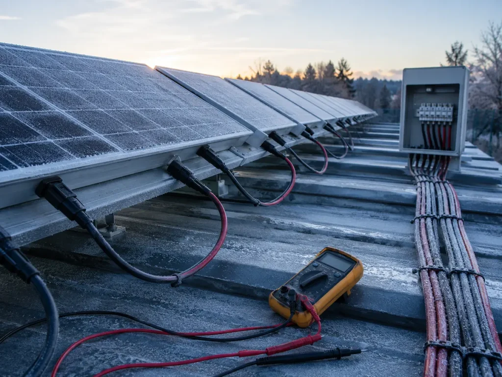
Series-connected modules add voltage. Start with the module Voc, multiply it by modules per string, and then correct it for the lowest expected cell temperature using the module manufacturer’s coefficient and the design method required by the project. PV voltage rises in cold conditions. The day used for the maximum-voltage check is therefore not the hot afternoon when the array is producing strongly; it is the cold condition that can push the open circuit toward a device limit.
Every component exposed to that circuit must suit the resulting maximum voltage. This includes fuse links and holders, breakers, SPD, switch-disconnector, busbar supports, terminals, monitoring parts, connectors, cable, and the enclosure’s internal insulation arrangement. A single 1,000 V component does not turn the full assembly into a 1,000 V product.
Leave design margin only in the way the governing rules and equipment instructions permit. Arbitrary margin can be too small to protect the project or so large that it hides a poor string arrangement. If the corrected Voc approaches the inverter or device ceiling, we stop and confirm the temperature basis rather than rounding the result down.
Keep string current and combined output current separate
A string input device sees the current and fault conditions assigned to that source circuit. The outgoing busbar, isolator, terminal, and cable can see the contribution from all parallel strings. Mixing those two numbers is one of the fastest ways to produce a box that looks plausible on paper but runs hot in service.
The applicable design method may apply a multiplier to module Isc and may require further correction for irradiance, continuous operation, temperature, grouping, or installation conditions. Cable ampacity and terminal ratings also change with ambient temperature and the number of loaded conductors in an enclosure. Use the local code and current project standard for the final factors. Do not treat a simplified online formula as the approval calculation.
Also compare the combined value with the inverter’s permitted input current and maximum short-circuit current for the assigned MPPT. The combiner can be electrically robust and still feed an input that was never meant to accept ten parallel strings.
Select string fuses around the module and conductor
Parallel strings can drive reverse current into a faulted string. Whether string overcurrent protection is required, and whether one or both polarities need it, depends on the parallel-string arrangement, module data, earthing system, cable protection, equipment instructions, and governing rules.
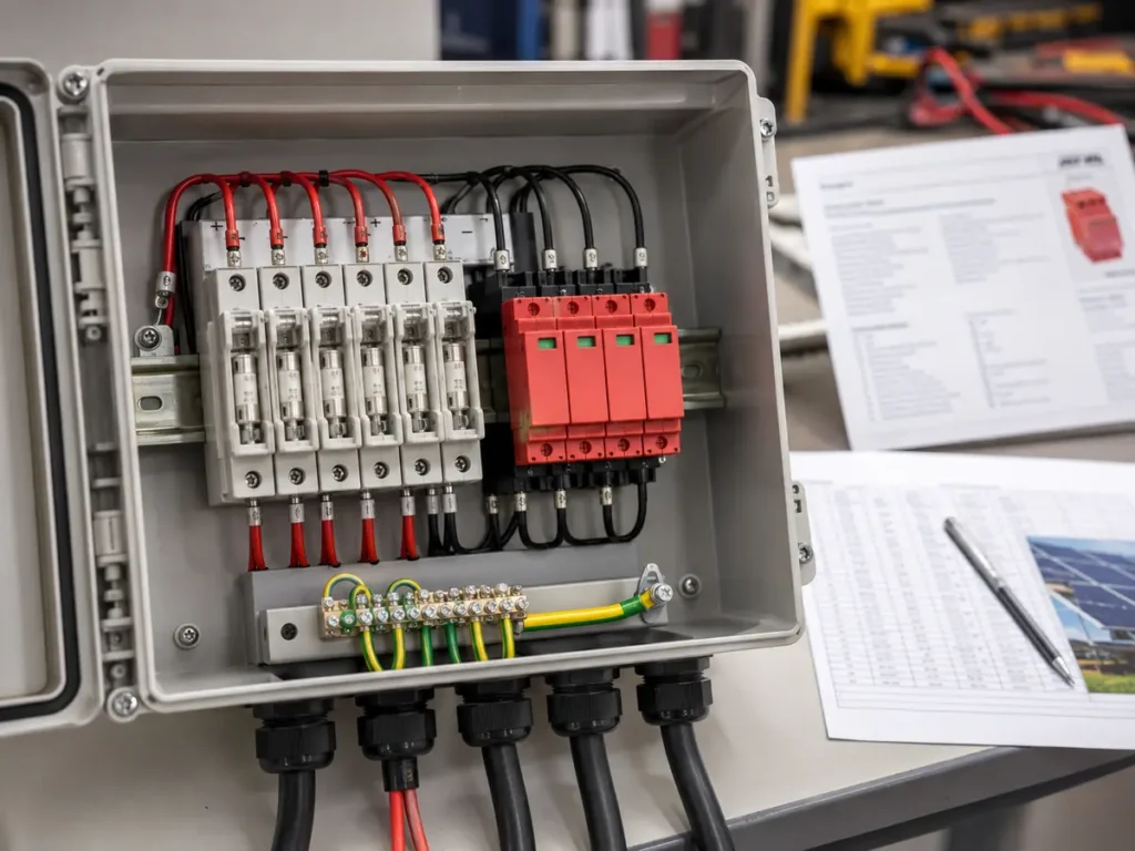
When fuses are used, the selected current must be high enough to avoid unwanted operation during expected PV output and low enough to stay within the module’s maximum series-fuse rating and protect the conductor. The link and holder must carry the system voltage, DC utilization, interrupting duty, ambient correction, and prospective fault conditions. We verify the pair together. An approved fuse link placed in a holder with a lower voltage or temperature rating leaves a quiet weakness in the assembly.
Replacement access matters too. A fuse holder is not an isolator unless its manufacturer and the installation design explicitly allow the intended operation. Labels and maintenance instructions should warn that PV conductors may remain energized in daylight.
Choose the PV SPD from voltage, system arrangement, and risk
The letters “Type 2, 1,000 V” do not finish an SPD review. Confirm that the device is intended for photovoltaic DC use, that its maximum continuous operating voltage suits the array under the required conditions, and that its protection mode matches the system earthing arrangement. Review nominal and maximum discharge current, voltage protection level, short-circuit behavior, backup protection, status indication, replaceable cartridge arrangement, and coordination with other SPDs.
Lightning protection on the building, cable route length, external exposure, separation distance, and regional lightning conditions can change whether Type 1 capability or coordinated devices are needed. The project’s lightning and surge protection assessment should make that decision. The IEC 61643-31 product standard covers SPDs for photovoltaic installations, while installation design must follow the applicable project rules and the selected SPD instructions.
Lead length can undo careful device selection. The route from live conductors through the SPD to the earth or bonding point should remain short and direct. Our related PV combiner box wiring diagram guide explains how those electrical choices should appear in the drawing and enclosure layout.
Size the DC isolator for real operating conditions
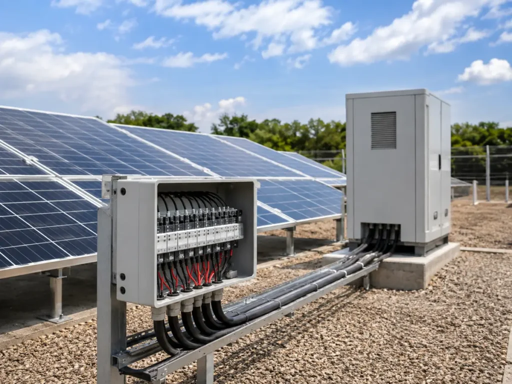
A switch-disconnector must interrupt and isolate the circuit arrangement shown on the approved diagram. Confirm rated operational voltage, current at the required utilization category, pole arrangement, series connection, load-breaking duty, thermal behavior, terminal capacity, and the enclosure temperature. The voltage and current shown separately on a catalog page may not apply together in the same DC-PV duty.
The combined array current is the starting point for an outgoing isolator, not the finish. Derating for enclosure temperature, mounting, adjacent devices, and manufacturer instructions may change the usable current. Check whether both polarities need switching and whether the proposed pole links match the manufacturer’s approved diagram. Never invent a series-pole arrangement to reach a higher voltage.
We also look at the handle and the person who will operate it. A lockable OFF position, clear indication, suitable IP performance, and enough room for the output cable can matter as much as the printed ampere value. For device-specific selection questions, our DC isolator switch guide covers the document and installation checks in more detail.
Review busbars, output protection, cable, and inverter limits
The busbar or distribution block carries the combined current. Check material, cross-section, plating, supports, temperature rise, short-circuit withstand, clearances, creepage, covers, and connection hardware. Then continue the same review through any output breaker or fuse, switch-disconnector, terminal, gland, lug, and cable.
Output overcurrent protection is project-specific. Its need and rating depend on conductor protection, equipment arrangement, fault contribution, inverter instructions, and local rules. A larger breaker is not a remedy for an undersized busbar or cable. Coordination should ensure that the intended device responds without placing another component beyond its rating.
Voltage drop deserves attention on long runs. The output cable must carry the design current after temperature, grouping, installation, and altitude corrections, while keeping loss within the project target. Confirm the actual conductor diameter and bend radius before approving the gland plate. Large DC cables are unforgiving when the drawing leaves them a narrow corner.
Illustrative review: ten strings into one output
Consider a review file with ten parallel strings. The module sheet lists Isc at 13.9 A and a maximum series-fuse rating of 25 A. The array calculation gives a cold-corrected maximum string voltage of 924 V. These values are only an example; the applicable current factors, device ratings, protection need, and design approval must come from the actual project.
The 924 V result immediately removes any component that cannot carry the required PV DC voltage with the necessary margin under the governing rules. For each string, the designer calculates the minimum protective rating needed to tolerate expected operating current, then checks that the result does not exceed 25 A or the protected conductor limit. If no suitable rating exists between those boundaries, choosing the nearest fuse is not a solution. The array or conductor design must return for review.
At the output, ten times 13.9 A gives 139 A before the project applies its required design factors. That arithmetic is useful, but 139 A is not yet an isolator order code. The design still has to consider maximum PV current, temperature correction, busbar rise, cable ampacity, inverter limits, and the selected device’s DC-PV utilization rating. A 160 A label may look comfortably above 139 A while the same switch has a lower usable rating inside a sun-warmed enclosure.
| Review point | Example input | What remains to be approved |
|---|---|---|
| Maximum voltage | 924 V cold-corrected string Voc | Voltage rating of every device, insulation arrangement and inverter limit |
| String protection | Isc 13.9 A; module maximum series fuse 25 A | Required design factor, conductor capacity, fuse link and holder ratings |
| Combined current | 10 × 13.9 A = 139 A before project factors | Design current, inverter input, busbar, isolator, terminal and cable ratings |
| SPD | PV DC circuit below the approved system ceiling | Ucpv, protection mode, type, discharge duty, backup and coordination |
| Enclosure | Ten inputs and one large output | Temperature, glands, bending space, access, IP and site environment |
Make sure the enclosure does not reduce the ratings
Outdoor exposure adds direct sun, ambient heat, condensation, ultraviolet light, dust, salt, rain, insects, and sometimes high altitude. Confirm the complete enclosure’s IP rating, material, UV resistance, corrosion performance, operating-temperature range, gland system, drainage or ventilation method, mounting orientation, and impact resistance where required.
Internal temperature can be higher than the weather report. Fuse holders, SPDs, terminals, monitoring power supplies, and switches all occupy space and may add heat. If the thermal review is missing, increasing the enclosure size or device current rating by guesswork gives no dependable answer. Use manufacturer loss data and the project’s thermal method, then confirm that wiring ducts and cable bundles do not block cooling or service access.
Before release, compare the calculation, single-line diagram, layout, bill of materials, label file, and test plan. Device codes and ratings must agree across all five. Production inspection should cover polarity, torque, earth continuity, insulation, switching, labels, glands, and enclosure condition. Buyers can also review UFELE’s quality control process and certificate information before order approval.
Send these records before requesting a final selection
- Exact module and inverter data sheets
- Modules per string and number of parallel strings
- Cold-corrected maximum Voc and current calculations
- Module maximum series-fuse rating and cable details
- Single-line diagram, MPPT allocation, and earthing concept
- Site temperature, altitude, lightning, and enclosure conditions
- Applicable standard, market, certificate, and label needs
- Monitoring, communication, output protection, and isolation requirements
Send the calculation sheet, array schedule, inverter manual, single-line diagram, site conditions, and destination market through the UFELE contact page. We can then review the missing conditions before a quotation turns into a production assumption.
Frequently asked questions
Can I size a PV combiner box from total array kW?
No. Array power does not show maximum string voltage, string current, parallel fault contribution, module series-fuse limit, inverter input limits, or environmental corrections. Use the exact module, string arrangement, inverter, site, and applicable design rules.
How is PV combiner box output current calculated?
Currents from parallel strings add at the combining point. The simple sum is only a starting value. The final design current must include the factors and corrections required by the governing standard, local code, conductor installation, environment, and equipment instructions.
Does every string need a PV fuse?
Not always. The decision depends on the number of parallel strings, possible reverse current, module maximum series-fuse rating, conductor protection, earthing arrangement, and applicable rules. When required, both the fuse link and holder must suit the PV DC circuit.
Can a 1,000 V SPD be used on every 1,000 V PV array?
No. Review the SPD’s PV suitability, maximum continuous operating voltage, protection mode, type, discharge ratings, backup protection, short-circuit behavior, coordination, earthing arrangement, and device instructions against the actual array.
Should the DC isolator equal the sum of string Isc?
The sum of string Isc is useful input, but it is not the complete isolator selection. Apply the project’s design-current method and check utilization category, voltage, pole arrangement, temperature derating, terminal capacity, load-breaking duty, and manufacturer instructions.
What documents should be approved before combiner box production?
Approve the calculation, single-line diagram, enclosure layout, bill of materials, device data, label file, and test plan. Keep module, inverter, drawing, and revision references consistent so a later component change triggers a fresh review.