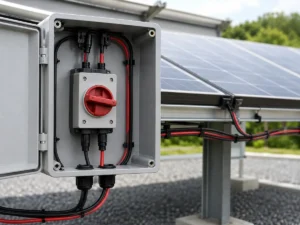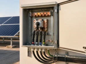
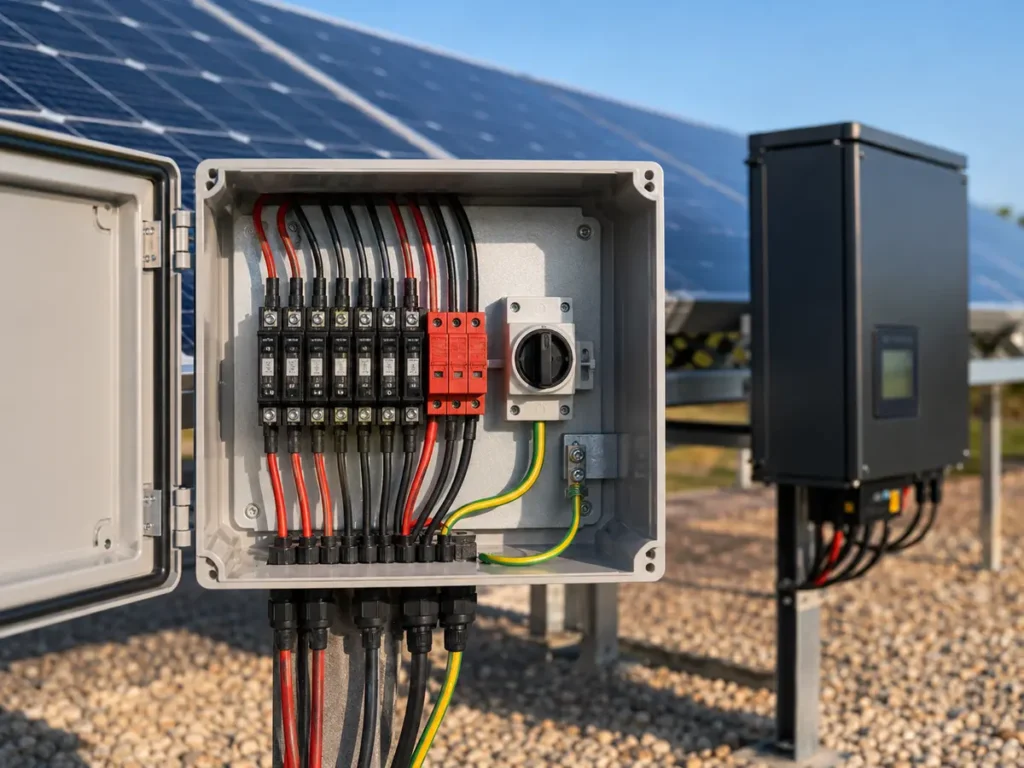
A neat enclosure photograph can be reassuring, but it does not tell us whether the current has a safe route through the box. When we review a PV combiner box wiring diagram, we follow every positive and negative conductor from the field cable to the outgoing terminals. We also look at the earth path, cable bends, heat, labels, and the space an electrician will need months later. That is where a drawing begins to feel like a real installation rather than a row of familiar components.
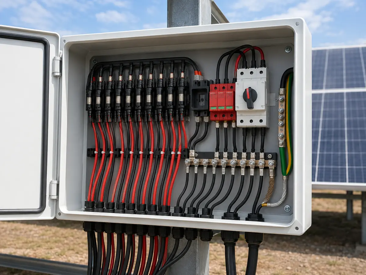
What does a PV combiner box wiring diagram show?
At minimum, it should show each PV string entering the enclosure, the positive and negative protection arrangement, the combining point, surge protective device connections, the protective earth path, the DC isolator when fitted, and the outgoing circuit to the inverter. It should also carry ratings, conductor sizes, polarity, terminal numbers, and device references. The order can vary with the project and local rules, so the approved single-line diagram and equipment instructions remain the final authority.
The box becomes uncomfortable to review when the drawing says “8 in, 1 out” and leaves everything else to imagination. Eight strings tell us the number of inputs. They do not tell us the maximum system voltage, expected current, available fault current, earthing arrangement, SPD type, or whether both polarities need switching or overcurrent protection. A price can be issued from that short description. A dependable build cannot.
UFELE supplies project-configured PV combiner boxes, but the enclosure is only one part of the protection plan. Before model approval, the buyer, designer, and manufacturer need to agree on the electrical ratings and the diagram revision. The electrician should not be asked to make those decisions after cables have already reached the site.
Start with the array and inverter, not the empty enclosure
We first ask for the module data sheet, string count, modules per string, cold-corrected maximum Voc, string Isc, conductor size, inverter input arrangement, earthing concept, and the applicable installation standard. The project location matters as well. Temperature, lightning exposure, altitude, dust, salt, humidity, and enclosure position can change the equipment and layout.
There is a small but costly trap here: a later panel change may keep the same wattage while changing Voc or Isc. The old combiner schedule then looks familiar enough to escape attention. We prefer to place the full module code and drawing revision beside the calculations. If procurement substitutes a module, the voltage, current, fuse, SPD, isolator, cable, and terminal checks return to the desk.
IEC 62548 addresses design safety requirements that arise from the characteristics of PV arrays. The project must also follow the current local code, inverter instructions, module instructions, and device manufacturer requirements. This guide explains how to review a drawing; it does not replace the approved engineering design.
| Project record | What we need to see | Why the drawing depends on it |
|---|---|---|
| PV string schedule | String IDs, modules per string, Voc, Isc, cable, and route | Sets circuit count, voltage, current, and identification |
| Inverter data | MPPT arrangement, input limits, allowed combining, and isolation needs | Prevents a combined output from exceeding one input or mixing trackers incorrectly |
| Protection study | Fuse or breaker ratings, SPD selection, fault-current assumptions, and coordination | Confirms that familiar devices are suitable for the actual DC circuit |
| Site and code basis | Location, environment, earthing, lightning system, and governing rules | Influences enclosure, SPD, bonding, cable entry, and installation details |
Give every string a traceable entry point
Each incoming pair should carry the same string identity used on the array drawing. We want an installer to trace “S03+” and “S03−” without opening three documents or guessing from cable position. Positive and negative terminals need unmistakable separation. Reversed polarity is not an abstract drafting error; it can damage equipment and places the commissioning team in a dangerous situation.
Bring the field cables into terminals or device connections approved for the conductor type and size. Check stripping length, tightening torque, ferrules or lugs, temperature rating, and the permitted number of conductors per terminal. A large enclosure does not rescue a terminal that was never designed to accept the cable.
Place string fuses or breakers where the design requires them
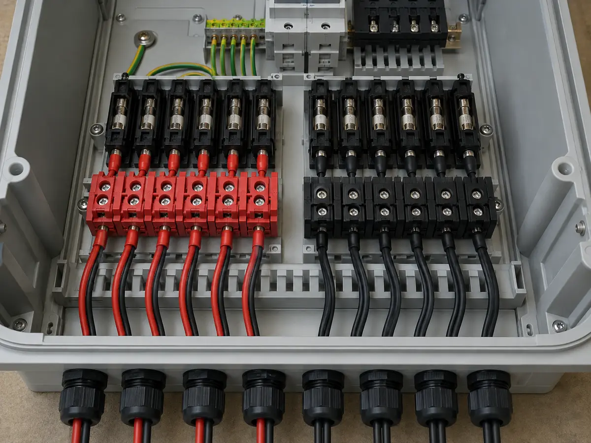
String overcurrent protection is not chosen from enclosure size. It follows the number of parallel strings, module maximum series-fuse rating, calculated current, conductor capacity, device standard, ambient conditions, and local rules. The drawing should identify the rating, pole arrangement, utilization category or DC suitability, interrupting capacity, and device reference.
Fuse holders deserve the same care as fuse links. A technician may eventually open one while searching for a weak string. The layout should provide safe access and clear identification, while the operating instructions state the isolation and test procedure. We do not want someone reaching across live outgoing conductors because the service space disappeared during layout.
Keep the SPD connection and earth path easy to follow
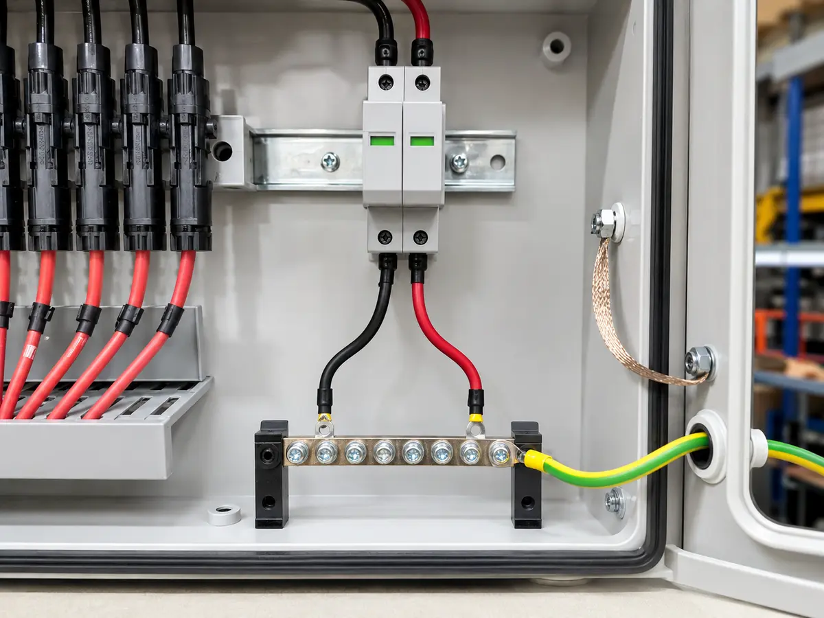
The surge protective device sits between the live PV conductors and the earthing or bonding system according to its approved connection scheme. Its maximum continuous operating voltage, PV suitability, protection mode, discharge rating, backup protection, and status indication must suit the project. The drawing should name the exact terminals. A generic SPD symbol leaves too much room for a costly assumption.
Layout matters because long, looping SPD leads add inductance and weaken the protection achieved at the equipment. We look for a short, direct route with sensible conductor separation and no decorative coils of spare wire. Phoenix Contact’s PV surge-protection guidance also describes surge currents being discharged toward ground potential through the combiner arrangement; the selected device manual and project lightning-protection concept should govern the final connection.
The protective earth bar needs a dependable connection to the enclosure and the project bonding system. Mark conductor sizes, terminal points, hardware, and any enclosure bonding strap. Paint, loose fasteners, or an unlabeled earth lead can turn a tidy green-and-yellow conductor into little more than visual comfort.
Show the combining point, DC isolator, and outgoing circuit
After individual strings pass through the required protection, their conductors meet at a busbar or approved distribution block. The part must carry the combined current and withstand the system voltage and fault conditions. Its supports, covers, clearances, and connections belong in the mechanical review, not just the bill of materials.
Where the design includes a DC switch-disconnector, the diagram must show what it isolates, how many poles it switches, and where it sits in relation to the SPD and outgoing terminals. The handle should remain usable after installation. Door interlocks, lockable OFF positions, and external operating handles need enough clearance to work as intended.
The output cable is often much larger than a string cable. Check lug size, bending radius, gland range, pulling direction, and the space below the switch or busbar. I become uneasy when a drawing leaves the largest conductor until last; that cable is usually the least willing to follow a beautiful tight bend.
Turn the circuit diagram into a serviceable enclosure
A single-line diagram explains electrical relationships. The enclosure layout decides whether people can build and maintain them. Keep positive and negative paths visually clear. Separate incoming string cables from outgoing conductors where practical. Give heat-producing devices room to dissipate heat, and respect the manufacturer’s clearance instructions.
Door depth can be forgotten when devices are arranged on a flat screen. Check handles, fuse carriers, cable ducts, terminal covers, SPD cartridges, and wire loops with the door closed. Then imagine replacing the SPD cartridge with gloved hands. If another component must be removed first, the layout is asking tomorrow’s technician to pay for today’s neatness.
| Layout zone | Review question | Common warning sign |
|---|---|---|
| String entry | Can every cable reach its terminal without crossing polarity zones? | Unlabeled cable bundle spread across live parts |
| Protection devices | Can fuses, breakers, and SPD cartridges be inspected or replaced safely? | Access blocked by output cable or door hardware |
| Earth path | Is the route short, direct, bonded, and visible? | Long loop sharing a crowded wiring duct |
| Output section | Is there enough gland, lug, bend, and pulling space? | Cable shown as a thin line with no bend radius |
| Thermal space | Do device clearances and enclosure conditions match the ratings? | Components packed tightly because the door still closes |
Treat cable entry as part of the protection design
Bottom entry often helps with water management, but the final choice depends on installation orientation, enclosure design, cable route, and gland system. Match every gland to cable diameter, material, environmental exposure, and ingress-protection requirement. Close unused openings with rated plugs. A high enclosure IP rating printed on a data sheet means little after someone drills an oversized hole and fills the gap with sealant.
Outdoor boxes also face condensation, ultraviolet exposure, insects, dust, salt, and heat. Drainage or ventilation features must be deliberate and compatible with the required enclosure performance. Place the box where technicians can approach it safely and where direct sun, floodwater, or irrigation spray will not create an avoidable burden.
Make the finished box match the drawing
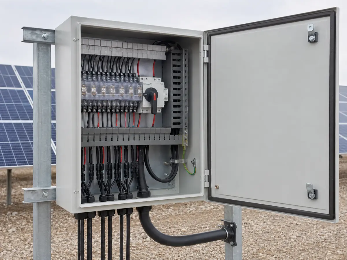
Label string terminals, protective devices, outgoing circuits, earth points, ratings, and hazards. Place a durable nameplate on the enclosure with the agreed model, system voltage, current, ingress rating, and drawing reference. The exact required markings depend on the market and standard, so confirm them before production rather than translating labels beside the packing bench.
Inspection should compare the physical box with the approved diagram and bill of materials. Check device codes and ratings, conductor colors and sizes, terminal torque, polarity, earth continuity, insulation, mechanical operation, clearances, glands, labels, and enclosure condition. Record the test result against the serial or order reference. Photographs help, but they do not replace measured results.
Layout mistakes that deserve a pause
Stop the drawing review when you find:
- String count without the module, voltage, current, or inverter basis
- Positive and negative conductors crossing without clear separation
- An SPD symbol with no device rating, terminal detail, or earth route
- Long SPD leads arranged around the enclosure for appearance
- Output cable size shown without gland, lug, or bend space
- Fuse holders or SPD cartridges blocked by other wiring
- Different MPPT inputs combined without inverter approval
- Unused holes, unsuitable glands, or missing enclosure bonds
- Labels that do not match the string schedule and test sheet
For project documents and device information, visit the electrical product catalog page. UFELE also supplies related solar energy equipment. Send the array schedule, inverter manual, single-line diagram, environmental requirements, and destination market through our contact page. We can then review the missing points before the enclosure moves into production.
Frequently asked questions
What is the normal wiring order inside a PV combiner box?
A common functional path runs from labeled PV string inputs through required string protection to a combining point, then through the specified isolation and output arrangement. The SPD connects according to its approved scheme and the project earthing design. Exact order and pole arrangement must follow the approved project drawing and local rules.
Does every PV string need a fuse?
Not automatically. The need and pole arrangement depend on parallel-string count, possible reverse current, module series-fuse rating, conductor protection, system earthing, device rules, and the applicable standard. A qualified designer should make the project-specific decision.
Where should the SPD earth conductor go?
It should follow the selected SPD manufacturer’s connection instructions and the project earthing and lightning-protection design. The route is normally kept short and direct to the appropriate earth or bonding point, with the specified conductor size and connection hardware.
Can positive and negative PV cables share one wiring duct?
The answer depends on the enclosure design and governing rules, but clear polarity separation and controlled routing make installation, inspection, and fault tracing safer. Avoid unnecessary loops and crossings, and maintain the required clearances and insulation.
Why is output-cable bend space important?
The combined output conductor can be much larger and stiffer than a string cable. Insufficient space can stress terminals, defeat the cable bend radius, interfere with the door, or force installers to rebuild the layout on site.
Is a combiner box photograph enough for approval?
No. Approval should use the electrical diagram, layout drawing, bill of materials, ratings, device data, label file, and test requirements. A photograph helps verify workmanship, but it cannot prove hidden connections, torque, insulation, or protection coordination.