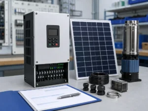
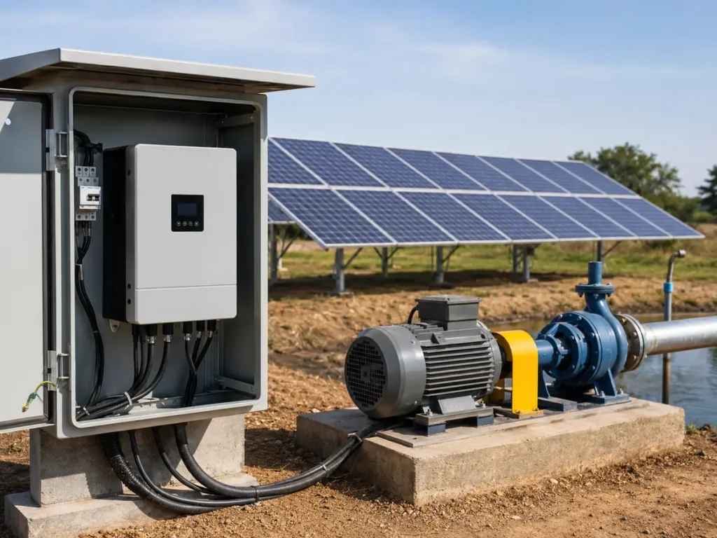
A reliable selection starts with the water duty and pump motor, not a quick comparison of kilowatts. This guide shows how to check motor current, output voltage, PV string voltage, temperature, operating head, and the information a supplier needs before confirming a model.
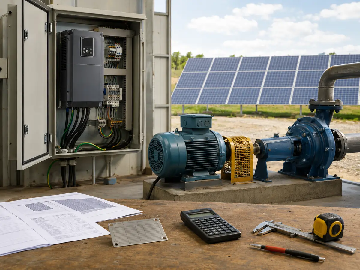
How do you size a solar pump inverter?
Read the motor plate before choosing an inverter size. Match the output-voltage class, then check that the drive can carry the motor’s rated current after any site derating. For the DC side, calculate the string voltage at operating temperature as well as the highest Voc expected on the coldest morning. The first value must stay within the drive’s working range; the second must remain below its maximum DC input limit. Array power, cabinet conditions, cable length, control signals, and protection can then be checked against the manual for the proposed model.
PV voltage and available power move throughout the day as sunlight and cell temperature change. The pump does not care why the input has changed; it still needs enough motor torque to lift water through the actual pipework. A workable inverter choice has to tolerate the PV variation while running that hydraulic load.
Motor kW only places the job in an initial size range. The nameplate current may differ between two motors marked with the same power because their voltage, efficiency, service factor, or winding design is different. Array wattage has a similar limitation: it says nothing about how many modules are in series, so equal-power arrays may present very different Vmp and Voc values to the drive.
UFELE offers a range of solar pump inverters for three-phase pump motors. The exact input range, output rating, enclosure, functions, and derating conditions depend on the selected series and model. Treat the method below as a selection workflow, not as a substitute for the model manual.
Step 1: establish the water duty before selecting electronics
Electrical sizing should wait until the pump duty makes sense. Note how much water the site needs, the required flow, static lift, likely drawdown, pipe loss, outlet pressure, and the seasonal low-water level. These figures establish total dynamic head. The selected pump must reach the required flow at that head on its published curve; changing the inverter later will not repair a poor pump selection.
Solar pumping adds a time dimension. The system may need to deliver a daily volume during a limited solar window rather than run at rated flow for 24 hours. Irradiance varies by location and season. Water demand can also peak in the month with weaker solar energy. Grundfos therefore recommends sizing around the critical month and using the project location, daily water requirement, and total dynamic head as core inputs in its solar pumping selection process.
Minimum hydraulic information
- Project location and the critical operating season
- Required water volume per day and preferred pumping hours
- Static water level and expected drawdown
- Vertical lift, discharge pressure, and pipe friction
- Total dynamic head and required flow at that head
- Pump model, pump curve, and allowable speed range
If these values are unknown, do not hide the gap by oversizing the inverter. Ask the pump supplier or system designer to establish a defensible duty point first. An oversized drive cannot make an undersized pump produce the required head, and an oversized pump can waste array capacity or operate outside a healthy part of its curve.
Step 2: read the pump motor nameplate
The motor nameplate is the starting point for the inverter’s AC output. Obtain a clear photo rather than a typed summary whenever possible. Confirm that the values belong to the actual motor supplied with the pump, not a similar catalogue model.
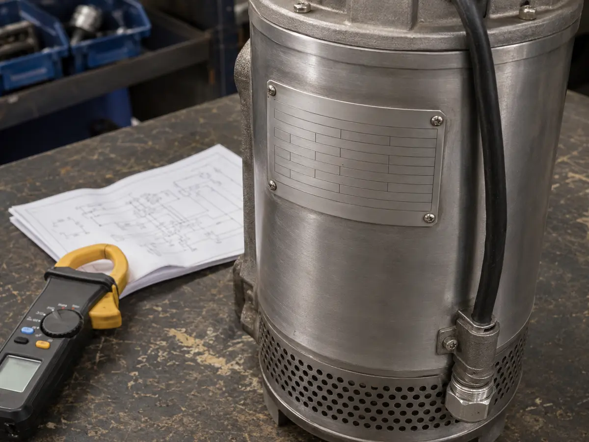
| Nameplate field | Why it matters | What to verify |
|---|---|---|
| Phase | Defines motor compatibility | Most solar pump drives in this class operate a three-phase motor |
| Rated voltage | Sets the required output-voltage class | Check the actual winding connection and permitted voltage |
| Rated current | Main continuous sizing reference | Use the value for the selected voltage and connection |
| Rated power | Useful initial model reference | Do not use kW alone to make the final choice |
| Frequency and speed | Define the rated operating point | Check 50/60 Hz data and pump speed limits |
| Power factor and efficiency | Help explain electrical loading | Use manufacturer data when the plate is incomplete |
A dual-voltage motor deserves special attention. For example, the plate may list different currents for different winding connections. Do not select from the lower current while wiring the motor for the other voltage. Also confirm whether the motor is intended for inverter duty and whether the pump manufacturer limits its minimum or maximum speed.
Step 3: size the inverter output by voltage and current
Begin with voltage compatibility. A drive must be able to produce the motor’s required three-phase output voltage from the available DC bus. A 380–415 V motor usually belongs with a corresponding output-voltage class; a 220–240 V motor belongs with another. Never assume the inverter can boost to any motor voltage merely because its input is solar DC.
Next, compare continuous output current. The inverter’s rated output current should not be lower than the motor rated current for the actual operating conditions. Current is often a stronger final check than kW because it reflects the electrical load the power stage must carry.
Any margin must follow the pump duty and the manufacturer’s rules. Centrifugal pumps usually have a predictable variable-torque characteristic, but real installations can still produce overload from high head, dense fluid, blocked piping, worn bearings, sand, or a pump operating away from its intended curve. Submersible motors may also have cooling requirements tied to water flow past the motor.
Also check overload capacity and operating mode. A catalogue may show a short-duration overload rating, but that rating does not turn a smaller drive into a continuously larger one. Dry-run recovery, sleep and wake cycles, and automatic restart settings can increase the number of starts. Confirm that the programmed behavior suits the pump and the water source.
Step 4: design the PV string around voltage limits
With the AC side checked, ask for the data sheet of the module that will actually ship. Record Vmp and Imp at maximum power, Voc and Isc, module wattage, and the voltage temperature coefficients. Do not copy values from a nearby model in the same series. A change in cell count or wattage can alter the string calculation even when the panels look identical.
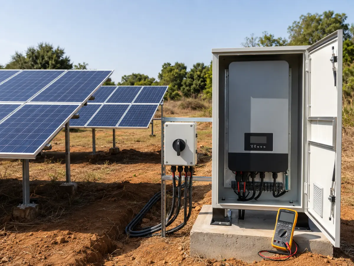
Check normal operating voltage
For one series string, a first estimate is:
String Vmp = number of modules in series × module Vmp
The temperature-adjusted operating voltage should remain inside the drive’s stated MPPT or working range during the intended pumping period.
If the operating voltage is too low, the drive may not start or may stop modulation as irradiance and cell temperature change. If it sits near the lower edge, hot modules can push it lower because module voltage falls as cell temperature rises. ABB’s solar pump firmware documentation likewise distinguishes minimum and maximum PV voltage limits and stops operation when DC voltage falls below the configured minimum.
Check cold-weather open-circuit voltage
Open-circuit voltage rises as modules become colder. The maximum expected string Voc must remain below the inverter’s absolute maximum DC input voltage. This is a hard safety and equipment limit, not an MPPT target. Use the module’s Voc temperature coefficient and the project’s lowest expected cell or ambient temperature according to the design method required for the site.
Cold string Voc = modules in series × module Voc × cold-temperature correction
Do not use the standard-test-condition Voc alone when the site can become colder than the test condition.
Check input current and parallel strings
Adding modules in parallel does not raise voltage; it increases available current. Confirm the drive’s maximum PV input current and any short-circuit-current limit. Then coordinate PV cable, connectors, isolators, fuses, breakers, surge protection, and combiner equipment with the array design and applicable installation rules.
Grundfos also notes that series and parallel arrangements must stay within the electrical specifications of the selected equipment. Its solar module guidance recommends matching the actual module information in the sizing process rather than treating all panels as interchangeable.
Step 5: check array power, temperature, altitude, and enclosure
Array wattage affects how often the pump can reach its required operating point and how much water it can deliver through changing sunlight. However, a large wattage number does not compensate for the wrong voltage window. Verify voltage first, then assess available power using project irradiance, losses, module orientation, shading, dust, temperature, cable loss, and the required water profile.
Some projects use a PV array whose nominal power is higher than the motor rating so that the system can run effectively outside peak sunlight. The acceptable array-to-drive ratio is product-specific. Never choose a ratio from a generic article without checking the inverter’s maximum PV power, input current, voltage limits, and supplier guidance.
A hot installation may reduce the continuous current available from the drive. At higher elevations, thinner air removes heat less effectively, and the manufacturer’s altitude limits may also address insulation clearance. For an outdoor site, specify how the equipment will be protected from rain, dust, sun, insects, and condensation. An IP20 model belongs inside a suitable enclosure. Use the expected temperature inside that enclosure for the derating check, since it can be much warmer than the weather reading outside.
Worked example: organize the checks before selecting a model
Take a project file with a three-phase pump motor marked 5.5 kW, 380 V, 50 Hz, and 12 A. The chosen 550 W module lists 41.8 Vmp and 49.8 Voc at standard test conditions. The designer has proposed a string of ten modules. Those figures are enough for an initial check, but not yet for model approval.
| Check | Illustrative result | Decision still required |
|---|---|---|
| Motor output | 380 V, 12 A, 5.5 kW | Look in the 380 V class and use the 12 A nameplate current as the load reference. Confirm that the proposed drive still covers it after derating. |
| String operating voltage | 10 modules give 418 Vmp at STC | Recalculate Vmp for the hottest expected module condition. That result, rather than 418 V alone, must fall within the drive’s working range. |
| String open-circuit voltage | 10 × 49.8 V = 498 Voc at STC | Calculate cold-corrected Voc and keep it below the absolute maximum |
| Nominal PV power | 10 × 550 W = 5.5 kWp | Model expected water output and confirm the permitted PV input power |
| Site conditions | Not yet supplied | Obtain temperature, altitude, shading, enclosure, head, flow, and seasonal data |
This example is deliberately incomplete. It shows why arithmetic alone cannot confirm a model. The string may look reasonable at standard test conditions but fail the hot-voltage or cold-Voc check. The drive may match 5.5 kW but not carry 12 A after temperature derating. The pump may also fail to deliver the daily water requirement at the actual head.
Step 6: include control, protection, and backup requirements
Two correctly sized drives can still be unsuitable for different control plans. State whether the project needs a float switch, tank level electrodes, pressure sensor, flow sensor, dry-run input, remote start, fault relay, analog feedback, RS485 communication, or scheduled operation. List the signal type and supply requirement instead of writing only “automatic control.”
For projects with weak seasonal sunlight or critical water demand, decide whether the system needs grid or generator backup. The input arrangement and changeover method must match the inverter design. Record the available backup source, voltage, phase, frequency, changeover method, and required operating priority in the sizing file.
Protection also belongs in the system design. Typical questions include DC isolation, PV string overcurrent protection where required, surge protection, earthing, AC output cable protection, motor cable length, and lightning exposure. Select devices for the actual DC voltage and prospective current. Follow local codes and the manuals for the inverter, pump, modules, and protection devices.
Common solar pump inverter sizing mistakes
1. Selecting only by motor kW
This ignores rated current, voltage, derating, overload duty, and motor connection. Use kW to find a starting range, then confirm current and conditions.
2. Using array wattage without checking string voltage
A 6 kWp array can be wired in several ways. Some arrangements may fall below the working range; others may exceed the maximum DC voltage.
3. Checking Voc only at standard test conditions
Cold modules produce a higher open-circuit voltage. Apply the module coefficient and site minimum temperature before approving the number of modules in series.
4. Ignoring the pump curve
The inverter controls speed, but the pump still follows its hydraulic characteristics. Confirm flow and head across the intended operating range.
5. Leaving temperature and altitude blank
A model that works in a cool test room may need derating inside a hot outdoor cabinet or at a high-altitude site.
6. Mixing data from different models
Enter the full pump, motor, module, and inverter codes in the project revision record. Do not shorten them. A missing suffix can point to another voltage, enclosure, or rating.
Solar pump inverter RFQ checklist
Once the technical inputs are available, the inquiry should be short and specific. The supplier should not have to infer the motor voltage from the country or estimate the array from a panel photo. A clear inquiry also makes quotations easier to compare.
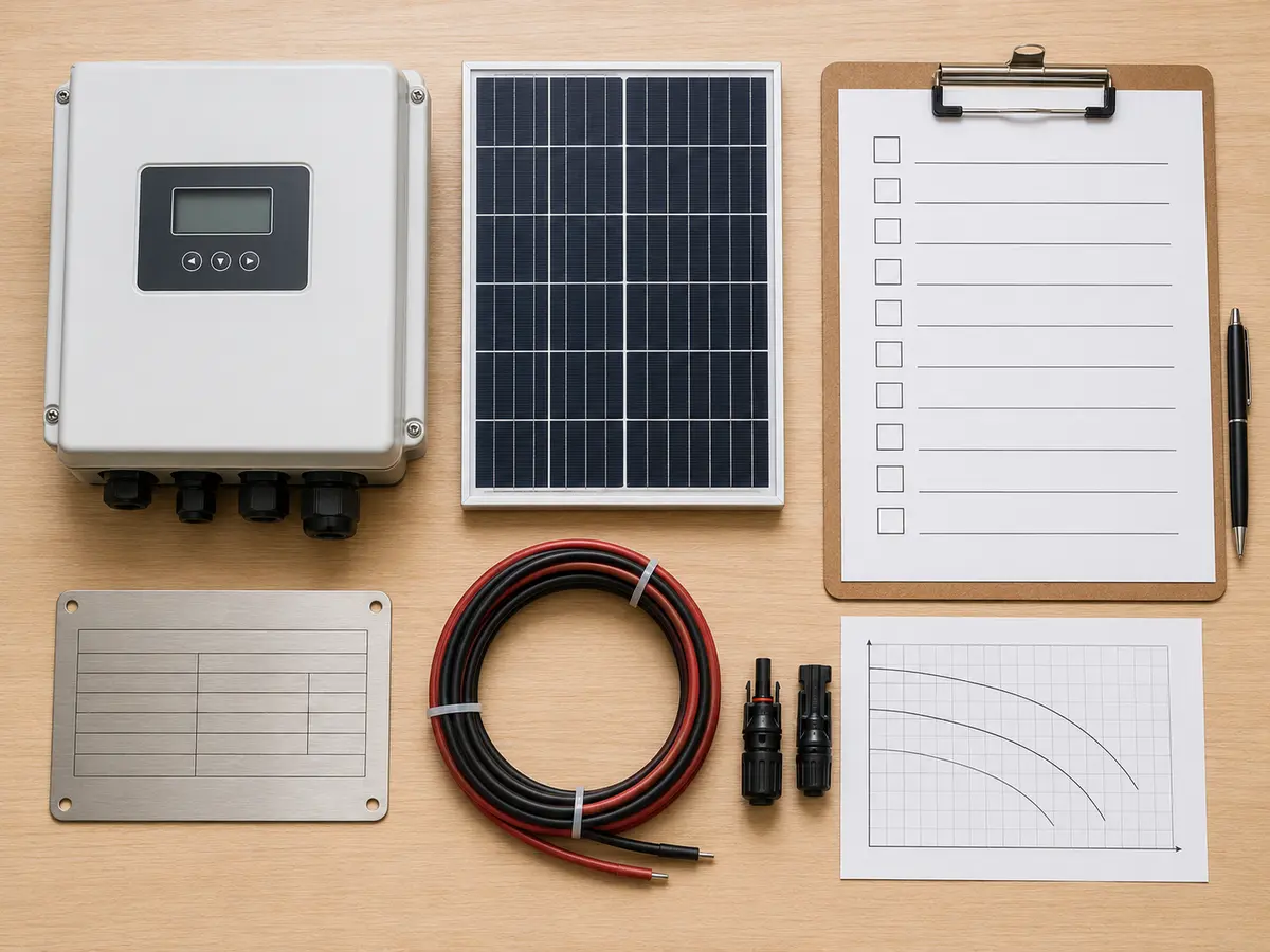
Send these details with the inquiry
- Pump and motor manufacturer, full model codes, curve, and nameplate photo
- Motor phase, voltage, rated current, power, frequency, and speed
- Required flow, total dynamic head, daily water volume, and application
- PV module data sheet, modules per string, number of strings, and total power
- Project location, minimum and maximum temperature, altitude, and installation position
- Required enclosure, control signals, sensors, communications, and backup source
- Motor cable length, protection plan, destination market, quantity, and documentation needs
Before sending the file, compare the numbers with the original photos and data sheets. If the pump motor plate is difficult to read, review the motor nameplate data required for pump drive selection. Mark assumptions clearly. A supplier can challenge an assumption; it cannot reliably correct a value that looks final but belongs to another model.
Prepare a model-specific selection
Send UFELE the motor nameplate, pump duty, PV module data, site conditions, control requirements, and estimated quantity. We can review the information against the relevant solar pump inverter series and identify any missing items before quotation.
Frequently Asked Questions
Solar pump inverter sizing FAQ
Can I select a solar pump inverter by motor kW alone?
No. Motor kW identifies a starting range, but you must also match phase, output voltage, rated motor current, duty, overload needs, ambient temperature, altitude, and the exact drive’s derating rules.
Should the inverter current be higher than the motor current?
The inverter’s applicable continuous output-current rating should cover the motor rated current under the actual operating conditions. Any extra margin or frame-size increase should follow the manufacturer’s selection and derating guidance.
How many solar panels can I connect in series?
Choose the series count so the temperature-adjusted operating voltage stays within the drive’s working range and the cold-corrected string Voc stays below its absolute maximum DC input voltage.
Can PV array power be greater than motor power?
Some systems use a higher nominal PV power to improve operation outside peak sunlight. The permitted ratio is model-specific and must remain within the inverter’s PV power, voltage, and current limits.
Why does total dynamic head matter to inverter sizing?
Total dynamic head determines the pump duty and affects required shaft power and current. If the head or pump selection is wrong, an electrically matched inverter cannot deliver the expected water volume.
What information should I send for a quotation?
Send the pump curve, motor nameplate, flow and head, PV module data, proposed string arrangement, temperatures, altitude, installation details, controls, cable length, backup source, quantity, and destination market.