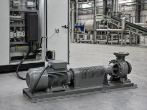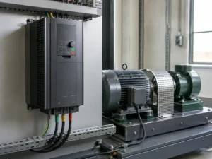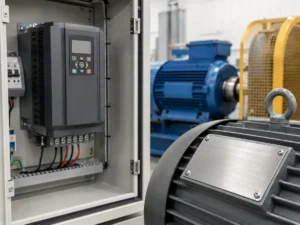
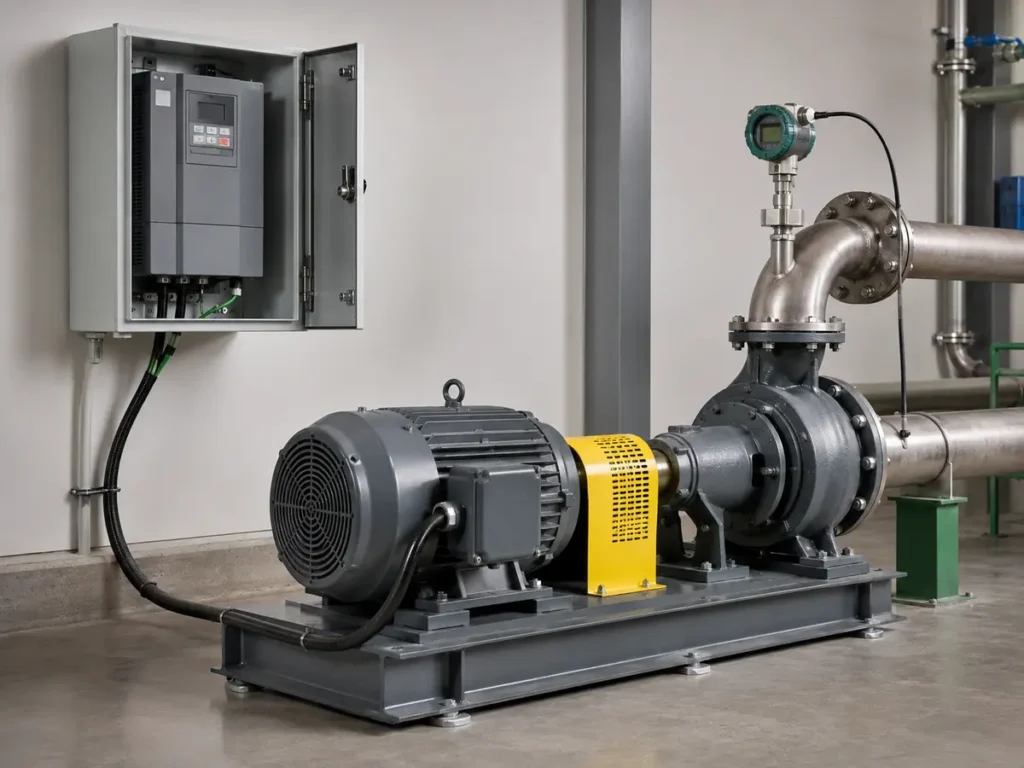
A pump does not care that the VFD catalogue shows the same kW as its motor. It responds to head, flow, suction conditions, valve position, and the demand elsewhere in the system. A sound selection joins those hydraulic facts to the motor current and the control plan. Miss that connection, and even a correctly powered drive can produce unstable pressure, poor flow, or a pump that runs hot at low speed.
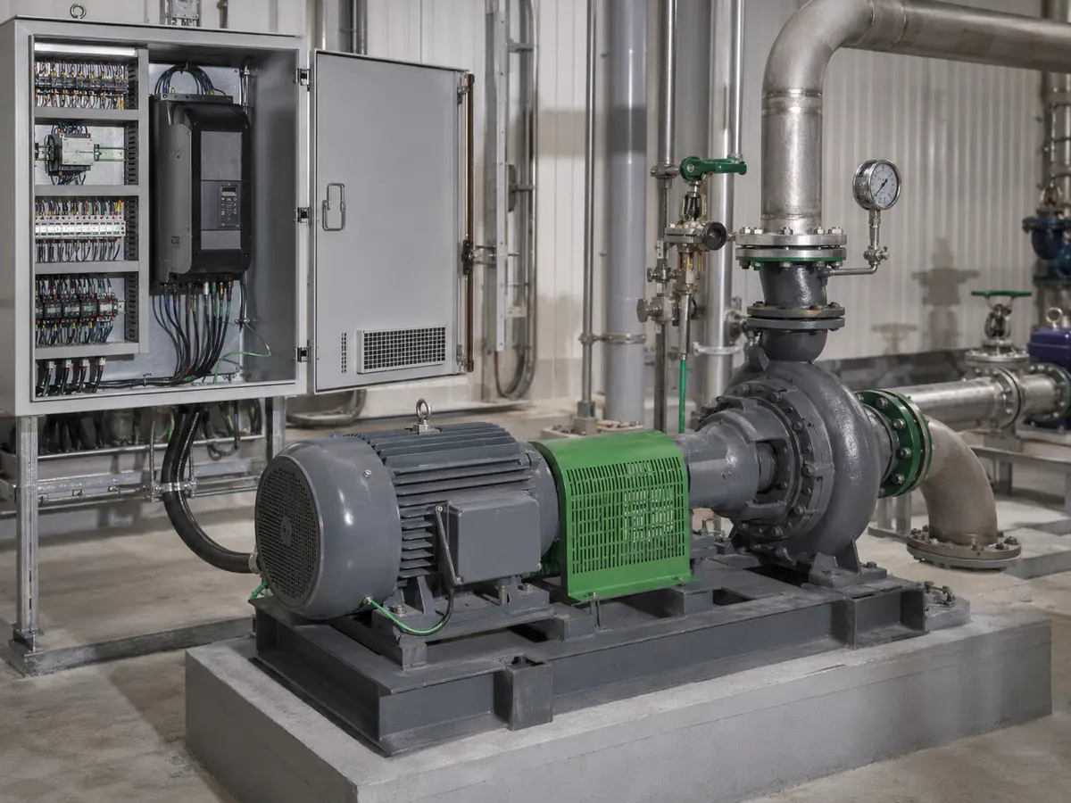
A useful pump VFD selection starts with four answers
Confirm the pump type, the required head-and-flow range, the motor’s full-load current, and the variable the system must control. Then choose a drive with the right voltage class and enough continuous output current after derating. Before release, verify the lowest safe pump speed, overload duty, sensor signal, PID functions, dry-run and low-flow protection, cable length, enclosure, and bypass or multi-pump logic. Motor kW remains a useful catalogue reference; it is not a hydraulic design.
One of the least satisfying commissioning calls begins with a sentence like this: “The VFD reaches the pressure setpoint, but the pump keeps speeding up and slowing down.” The drive is alive. The motor turns. Nothing looks obviously wrong. Yet the pressure needle refuses to settle, a check valve chatters, and everyone starts changing PID numbers without knowing what the system is asking the pump to do.
That situation rarely begins with one bad parameter. Sometimes the pressure sensor sits in a turbulent location. Sometimes the selected minimum speed cannot overcome the static head. A large pump may serve a demand that becomes tiny at night, so it has no stable low-flow operating point. In another project, a bypass valve quietly sends water back to the tank while the controller tries to correct a pressure loss it can never understand.
In this setting, a VFD for pumps gives the system a flexible motor-speed control tool. It cannot repair a weak hydraulic concept. The most reliable projects treat the pump, pipework, motor, sensor, drive, and operating sequence as one system.
Begin with the job the VFD must perform
“Control the pump” is still too broad. Write down what the process must hold steady and what is allowed to change. That short description becomes the control philosophy. It also tells the supplier whether the drive needs a simple speed reference, an internal PID loop, PLC communication, or dedicated pump functions.
| Process objective | Typical feedback or command | Question that changes the design |
|---|---|---|
| Constant discharge pressure | Pressure transducer, often 4–20 mA | Should pressure remain constant at the pump outlet or at a remote critical point? |
| Constant differential pressure | Two pressure signals or one differential transmitter | Will control follow the pump, a filter, or the far end of a closed loop? |
| Flow regulation | Flow meter or PLC flow command | How quickly can demand change, and how accurate must the flow be? |
| Tank or sump level | Level transmitter, floats, or staged level contacts | Is the goal smooth level control, emptying, filling, or protection against overflow? |
| Operator or PLC speed demand | Keypad, analog signal, fieldbus, or digital presets | Who owns start, stop, setpoint, alarm reset, and local/remote selection? |
Do not select the sensor after the cabinet has been built. Its range, accuracy, supply, signal type, mounting point, and failure behavior belong in the control design. A 0–16 bar transmitter in a system that normally operates around 1 bar may deliver a poor working signal. A good sensor with the wrong range can make a well-sized drive look nervous.
Not every pump is a variable-torque load
Most conversations about a VFD for pumps assume a centrifugal pump. That is reasonable for water supply, HVAC circulation, irrigation, cooling, and many process services. For a centrifugal pump, the torque demand generally falls as speed falls, so a normal-duty or variable-torque drive rating may fit.
Positive-displacement pumps need a different review. Gear, screw, piston, diaphragm, and progressive-cavity designs can demand approximately constant torque across their speed range. Their discharge pressure comes mainly from system resistance rather than the pump creating a fixed head curve. Blocking the discharge can raise pressure dangerously, so an appropriate relief path and the pump manufacturer’s operating limits remain essential. A VFD is not a substitute for a relief valve.
Also check the pump’s actual duty, not its family name alone. A submersible borehole pump may have motor-cooling requirements tied to water velocity. A slurry pump may face solids settling below a certain speed. A lubrication pump can have a minimum pressure that the process must receive immediately. Those limits can remove much of the attractive speed range shown on a VFD keypad.
Put the pump curve and system curve on the same page
A pump curve shows how a specific pump and impeller behave at a stated speed. It normally relates flow to head and may also show efficiency, absorbed power, and net positive suction head required (NPSHR). The system curve represents the head that the installation requires at each flow. Where those curves cross, the pump finds its operating point.
This matters because the VFD changes the pump curve by changing speed. The system curve does not simply follow it. Static head—the vertical lift or fixed pressure difference—remains when the flow approaches zero. Friction head changes with flow. In a system with little static head, reducing speed can shift the operating point smoothly. In a high-lift system, a modest speed reduction may leave too little pump head to move any water at all.
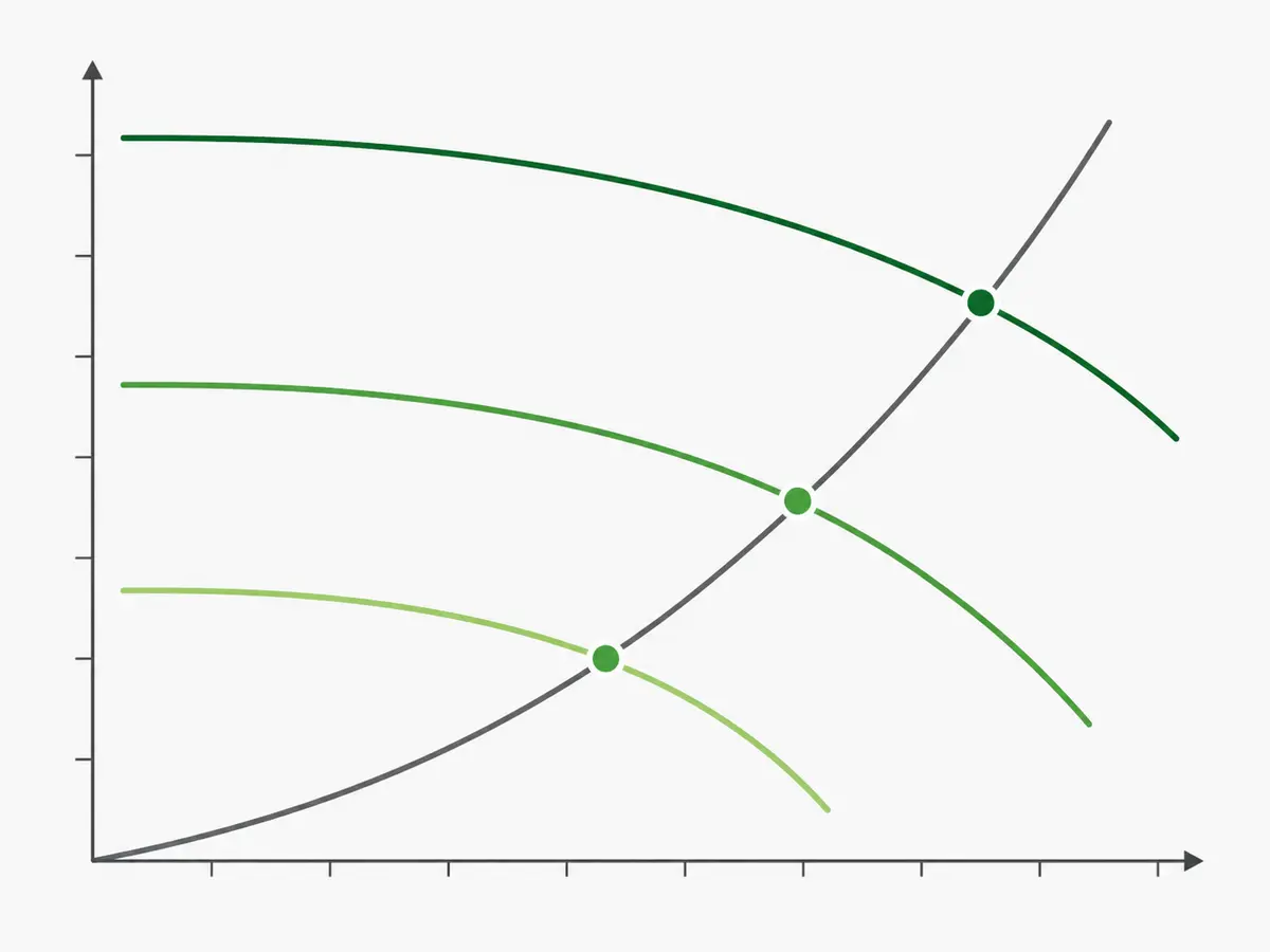
Ask for more than the nominal duty point. The design team should identify the minimum, normal, and maximum required flow and head, along with credible valve and tank conditions. Add the pump’s permitted operating region, minimum continuous stable flow, maximum power, and motor limit. If the pump manufacturer supplies reduced-speed curves, use them. If not, qualified engineers can make an initial estimate with the affinity laws and then check it against the actual system.
Size a VFD for pumps from motor current and pump duty
Once the hydraulic operating range makes sense, move to the motor and power supply. Record the supply voltage and phase at the site. Obtain a readable motor nameplate photo. The motor’s rated voltage, full-load current, frequency, power, speed, connection, efficiency, and motor type should agree with the proposed drive and wiring.
Use the VFD’s continuous output-current rating as the main sizing check. It must cover the motor and application after any derating for ambient temperature, altitude, enclosure, switching frequency, or input arrangement. Catalogue kW columns make comparison easier, but motors with the same output power do not always carry the same current.
Centrifugal pumps usually start with low load when the VFD ramps them from zero speed. They rarely need the same short-term overload rating as a crusher or loaded conveyor. That does not justify removing all current margin. A blocked pipe, dense process liquid, worn pump, wrong impeller, or operation beyond the intended flow can push the motor toward overload. Select against documented current and duty ratings, not an assumption that “pumps are easy.”
For a positive-displacement pump, review constant-torque current, breakaway torque, acceleration, viscosity at the coldest start, and pressure relief. It may require the drive’s heavy-duty rating or a larger model. This is one reason a generic pump kW table can mislead buyers.
Input details that can change the model
- Single-phase supply: use a drive explicitly approved for that input and follow its sizing or derating rule.
- Generator or weak network: state the generator rating, transformer capacity, voltage variation, and other large loads that switch nearby.
- Existing capacitor bank: do not leave power-factor correction capacitors between the VFD and motor.
- Motor already in service: include the old drive model, alarm history, measured running current, and actual pump duty if they are available.
The lowest frequency is a pump decision, not a default parameter
Many drives arrive with a broad frequency range. That range says what the electronics can command; it does not say where the pump should operate. Set minimum and maximum speed only after checking the hydraulic and mechanical limits.
At low speed, a centrifugal pump may fail to overcome static head. Water then stops moving even though the shaft continues to turn. The liquid inside the casing can heat, internal recirculation can increase, and seals or bearings may suffer. At the motor, a shaft-mounted cooling fan also moves less air. Submersible motors may depend on minimum flow past the motor body for cooling.
The maximum limit deserves equal care. Raising frequency above the motor’s base frequency does not preserve constant torque. Pump absorbed power can climb quickly with speed, and the pump or motor may exceed its mechanical, power, pressure, or NPSH limit. Never use overspeed as an easy answer to an undersized pump without written approval from the pump and motor manufacturers.
Good low-demand control often combines a minimum running speed with a sleep function. If demand remains below the stable range, the drive can stop the pump after pressure has been satisfied and restart it when pressure falls. A pressure vessel, check valve, leakage rate, restart delay, and wake threshold all influence whether this works smoothly. Poor settings trade continuous low-flow operation for rapid start-stop cycling—hardly an improvement.
PID control works only when the feedback tells the truth
Closed-loop pressure or flow control compares a measured value with a setpoint and changes pump speed to reduce the error. Many pump applications can use the PID controller inside the VFD. More complex plants may let a PLC coordinate the loop, interlocks, and multiple pumps. The correct choice depends on who must own the operating sequence and how the rest of the plant communicates.
Sensor location changes what “constant pressure” means. A transducer beside the pump keeps discharge pressure steady at that point. A remote sensor can protect pressure at the critical user after pipe friction, but it adds cable, signal, access, and failure considerations. Differential-pressure control may suit a closed circulation loop better than a single discharge reading.
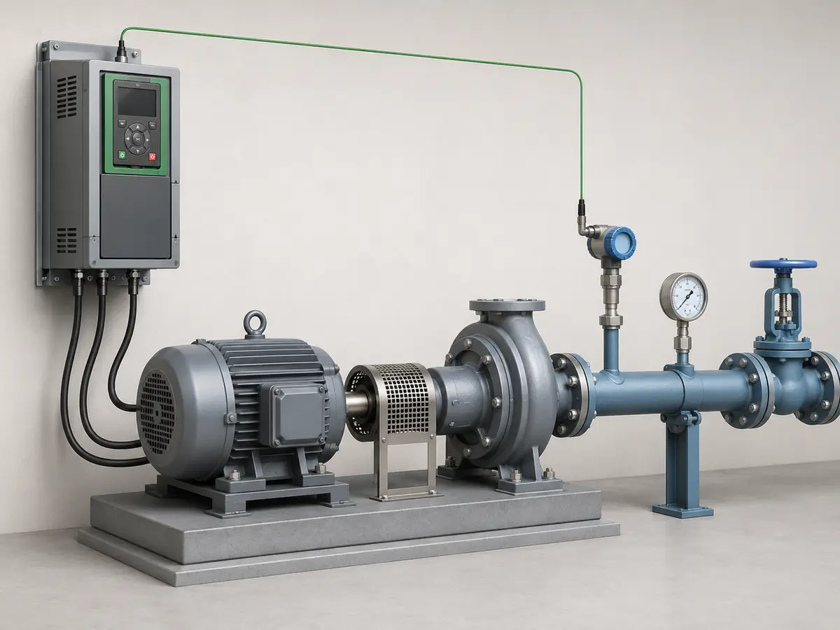
Commissioning should begin gently. Confirm the sensor scaling and direction before tuning. If increasing pump speed makes the measured value move the wrong way, no PID value will rescue the loop. Then check the minimum and maximum outputs, ramp times, and the response with realistic demand changes. Excess proportional gain can make the system hunt. Too much integral action can carry the speed past the setpoint and create a slow oscillation. No universal set of PID numbers fits every pipe network.
Decide what happens when feedback disappears or moves outside a credible range. Should the drive stop, run at a safe preset speed, transfer control to a PLC, or raise an alarm and wait? The process risk—not convenience—should decide. Our separate guide to VFD control methods compares keypad, terminal, PLC, analog-feedback, and PID arrangements in more detail.
Pump functions worth discussing before purchase
- Dry-run or underload protection: confirm how the function detects loss of water and validate it across the real operating range.
- Sleep and wake control: define minimum speed, pressure boost, stop delay, wake level, and restart delay.
- Pipe-fill mode: limit the initial pressure rise when filling an empty network.
- Broken-pipe or leakage response: decide what high speed with low pressure should trigger.
- Anti-jam or cleaning sequence: use it only if the pump manufacturer permits the direction and speed changes.
- Run-time and alarm logging: decide which values maintenance staff need locally or through the PLC.
Use the affinity laws as a guide, not a savings guarantee
Variable speed can save substantial energy when a centrifugal pump serves changing demand, especially where friction head dominates and a valve currently throttles excess flow. Under geometrically similar conditions, the pump affinity relationships provide a useful first estimate:
Ideal affinity-law relationships
Flow changes approximately in proportion to speed: Q2/Q1 = N2/N1. Head changes approximately with the square of speed: H2/H1 = (N2/N1)2. Pump power changes approximately with the cube: P2/P1 = (N2/N1)3.
At 80% speed, the ideal cube relationship gives 0.83, or 51.2% of the original pump power. That is not a promise that the electricity meter will fall by 48.8%. Static head, pump efficiency, motor and drive losses, control margins, and the actual duty profile change the result.
The strongest estimate uses measured operating hours, flow, pressure, valve position, and input power across the load profile. It compares the existing control method with the proposed variable speed operating points. A pump that already runs near its best operating region at steady full demand may offer little energy saving. An oversized pump that spends most of its life against a partly closed valve is a much better candidate, although trimming the impeller or replacing the pump may also deserve study.
The U.S. Department of Energy’s Variable Speed Pumping guide explains the interaction between pump curves, system curves, and affinity laws. The Hydraulic Institute also provides a practical introduction to pump curves and operating points. These references support system-level assessment; the exact pump and drive manuals still govern the equipment limits.
Multiple pumps need a sequence, not several independent PID loops
A broad demand range often works better with two or more pumps than with one large pump forced to cover everything. In a booster set, one lead pump can vary speed while additional pumps start as demand rises. At low demand, the sequence removes lag pumps and lets one unit operate in a useful range. Rotation can share run hours and keep standby pumps exercised.
The staging thresholds need hysteresis and time delays. Without them, a lag pump can switch on, lift the pressure, switch off, and repeat. The system should also define what happens when one drive, motor, sensor, or pump becomes unavailable. Critical water service may justify redundant sensors, a standby pump, a common controller, manual modes, or an emergency bypass. Redundancy must be designed; adding a bypass switch to the drawing does not create it.
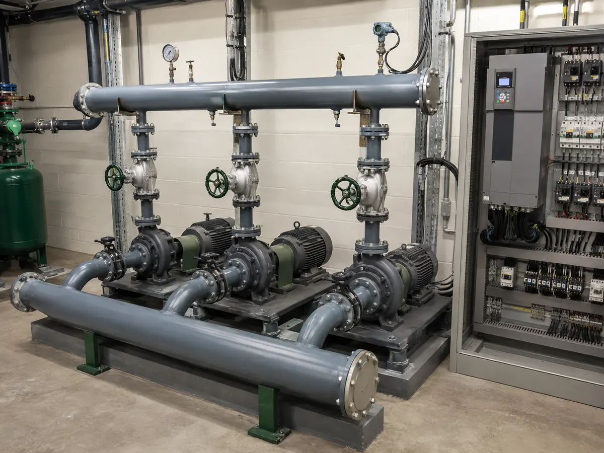
One VFD can sometimes transfer between multiple motors, or run motors together, but those arrangements require careful switching, motor protection, parameter, and isolation design. Never open or close the VFD-to-motor circuit as though it were an ordinary direct-on-line feeder unless the drive manufacturer approves the sequence.
Finish the electrical and environmental design before ordering
Pump rooms are not always kind to electronics. State the highest ambient temperature, humidity, condensation risk, altitude, chemical vapors, dust, and washdown exposure. Decide whether the VFD will sit in a clean control room, a ventilated cabinet, or near the pump. The IP rating on a drive does not excuse poor cable glands, blocked airflow, or mounting it where a leaking seal can spray the enclosure.
Record the motor cable type and length. A long cable can increase reflected-wave voltage, leakage current, electromagnetic interference, and stress on the motor insulation. The final design may need shielded cable, an output reactor, a dV/dt filter, a sine-wave filter, lower carrier frequency, or a different mounting arrangement. Follow the drive and motor limits rather than using a single cable-length rule for every product.
Earthing, shielding, input protection, isolation, and EMC practice should follow local codes and the manufacturer’s instructions. Add any required fieldbus, analog inputs, relay outputs, safety functions, panel meters, and remote keypad to the inquiry. If a bypass is required, describe whether it is for maintenance or emergency direct-on-line operation. A direct-on-line bypass can create high starting current and pressure transients that the VFD normally avoids.
Worked example: a building booster pump with variable demand
What the first inquiry says
The buyer has a 22 kW, 400 V centrifugal booster pump. The motor plate shows 41 A. The pump must maintain pressure for a building where demand changes sharply between morning peak and night. That information points in the right direction, but it still does not finish the selection.
What the engineer asks next
We need the pump curve and impeller diameter, the required minimum and maximum flow, the pressure setpoint, static head, suction conditions, current valve-control method, cable length, ambient temperature, and sensor plan. Night demand matters because the pump may fall below its minimum stable flow. The owner also needs to decide whether water service can stop if the VFD fails.
How the preliminary VFD choice develops
Start with a 400 V-class drive whose normal-duty continuous output current covers 41 A after site derating. Then verify that the reduced-speed pump curve can satisfy the system above its static head. Establish a minimum running speed from the pump maker’s operating region and motor cooling requirements. If night demand falls below that region, use a pressure vessel and properly commissioned sleep/wake sequence rather than letting the pump turn slowly with almost no flow.
What commissioning must prove
Check rotation first. Scale the pressure transducer, confirm the control direction, and test feedback failure. Tune the loop with realistic valve changes, then test sleep, wake, dry-run response, high- and low-pressure alarms, and restart after a power loss. Record motor current, output frequency, pressure, and flow at several demand points. That record is more valuable than a photograph of a drive showing 50 Hz and no load context.
This example does not produce a universal model number. It shows why the 41 A plate value and pump duty belong in the same review. If the same 22 kW motor drove a positive-displacement pump handling cold viscous liquid, the duty rating, acceleration, torque, and protection discussion would change considerably.
A standard pump VFD and a solar pump inverter solve different input problems
A conventional VFD normally receives a stable AC supply and varies motor frequency and voltage. A solar pump inverter can accept a PV array input and use solar-specific control such as maximum power point tracking. It must coordinate changing irradiance with pump demand, motor limits, and water availability. Some systems also accept grid or generator backup, but that capability depends on the product architecture.
Do not choose between them by the word “pump.” Choose from the available energy source and system objective. Our solar pump inverter vs VFD comparison keeps those two selection paths separate.
The pump VFD inquiry list that prevents a second round of guessing
A useful inquiry does not need a long report. It needs the few documents and operating facts that reveal the system. Send the clearest information first and mark unknown values instead of filling gaps with estimates that look final.
- Power supply: voltage, phase, frequency, generator or transformer details, and known voltage variation.
- Motor: readable nameplate photo, cable length, motor type, and existing protection or forced ventilation.
- Pump: manufacturer, model, impeller diameter, pump curve, pump type, and permitted operating range.
- Duty: minimum, normal, and maximum flow and head; static head; liquid type, temperature, density, and viscosity when relevant.
- Control: pressure, differential pressure, flow, level, or speed objective; setpoint range; sensor type and location.
- Sequence: start/stop owner, local and remote modes, sleep/wake, dry-run action, alarms, restart behavior, and bypass requirement.
- Multiple pumps: number of pumps, common or separate headers, lead-lag plan, staging logic, and required redundancy.
- Installation: ambient temperature, altitude, humidity, dust, chemicals, enclosure location, EMC needs, and communication protocol.
If the project is still at concept stage, send the pump curve, motor plate, expected duty range, and a simple piping sketch. Those four items usually reveal which questions deserve attention next. UFELE’s broader electrical solutions page shows how drive selection connects with pump control, solar pumping, and electrical protection. When we review a VFD for pumps, the site conditions matter just as much as the kW line in an initial price request.
Prepare a clearer VFD inquiry
Send the pump curve, motor plate, and control target
We can review the voltage class, continuous current, duty type, feedback needs, installation conditions, and the functions that should appear in the quotation. Final hydraulic approval remains with the pump and system designer.
Pump VFD FAQ
Questions that usually appear before model approval
These answers cover common starting points. The pump curve, motor plate, hydraulic limits, and exact drive manual decide the final design.
Should a pump VFD be sized by kW or motor current?
Use motor kW to identify the preliminary range, then confirm the VFD by continuous output current, voltage class, duty rating, and derating. The drive’s usable current must cover the motor and application under the site conditions.
Can every centrifugal pump run at very low speed?
No. The pump still needs enough speed to overcome static head and remain within its permitted operating region. Minimum stable flow, internal recirculation, motor cooling, solids, lubrication, and process requirements can set a higher limit.
Where should the pressure sensor be installed?
Install it where the pressure must be controlled. That may be near the pump outlet or at a remote critical point. The final location must also provide a representative, maintainable signal without excessive pulsation or electrical noise.
Does a VFD always save energy on a pump?
No. Savings depend on the load profile, static and friction head, current control method, pump efficiency, and time spent at reduced demand. Variable speed is often attractive when a centrifugal pump is throttled for long periods, but measured system data should support the estimate.
Can one VFD control several pumps?
It can in some engineered arrangements, including lead-lag or cascade systems, but switching, interlocks, motor protection, parameters, and failure modes need a defined sequence. Separate drives often provide greater control and redundancy.
Is a VFD suitable for a positive-displacement pump?
It can be, provided the drive is selected for the pump’s constant-torque demand and the system retains suitable pressure relief. Check starting viscosity, minimum and maximum speed, lubrication, cooling, and the pump manufacturer’s limits.