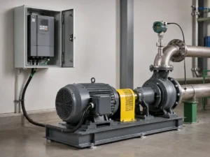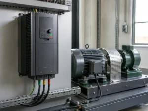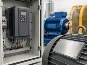
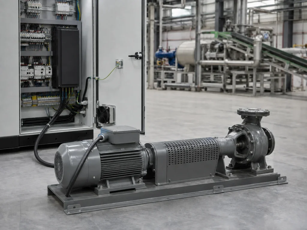
A motor’s kW rating narrows the field, but it cannot choose the drive for you. Think about two 15 kW machines: a lightly loaded fan and a conveyor that must restart with product already on the belt. Their nameplates may look similar, but their starting torque, low-speed duty, and overload demands are not. The cabinet and the site can rule out a drive as well.
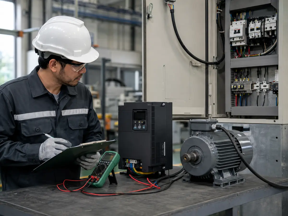
Short answer: choose the VFD by current and duty, then verify everything around it
Start with the machine, not the VFD catalogue. Find out what the motor drives, whether it starts empty or loaded, and where the machine must run between its lowest and highest useful speeds. A clear motor-plate photo should settle the voltage, rated current, frequency, speed, and motor type. From there, compare the drive’s usable output current with the application demand after duty and site derating. Acceleration, braking, low-speed motor cooling, control method, enclosure, cable length, EMC, and communication still need answers before the model is final. Until those details are known, a matching kW figure supports only a preliminary quotation.
A quotation can look perfectly tidy and still contain the wrong drive. The model may show the same 15 kW rating as the motor. The voltage may appear correct. The price may even match the budget. Then commissioning starts, the conveyor fills with material, and the drive trips during acceleration.
We see this risk when an inquiry contains only two lines: “15 kW motor, 380 V, need VFD.” Those details do not describe the work. A lightly loaded centrifugal fan and a loaded screw conveyor can use motors with the same nameplate power, yet they place very different demands on a drive. One mainly needs smooth variable-speed control. The other may need high breakaway torque and repeated overload capacity.
Good variable frequency drive selection starts with the process. It then moves through the motor, power supply, control method, and installation. The order matters because each answer can change the required current rating or drive function.
1. Describe the load before looking at a VFD model
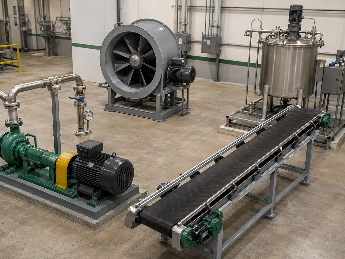
Begin with one plain question: what does the motor actually move? The answer is more useful than the motor kW because it reveals how torque changes with speed. It also points to starting, stopping, and overload demands.
| Load pattern | Common examples | What matters during selection |
|---|---|---|
| Variable torque | Centrifugal pumps and fans | Operating point, minimum and maximum speed, PID control, and continuous current |
| Constant torque | Conveyors, mixers, extruders, and positive-displacement pumps | Can the drive start the machine under load and hold the required torque at its lowest working speed? Check motor cooling, the requested acceleration time, and the model’s heavy-duty current rating. |
| Constant power | Winders, unwinders, and some machine-tool spindles | Confirm where base speed ends, how far the field-weakening range must extend, and what torque remains at each commanded speed. Feedback requirements and the motor’s mechanical limits often decide the answer. |
| High breakaway or shock load | Loaded conveyors, crushers, and some reciprocating machines | Use the worst restart or impact, not the smooth running condition. Quantify the breakaway torque, load inertia, possible jams, and how long and how often the peak returns. |
| Overhauling load | Hoists, downhill conveyors, and descending vertical loads | Regenerative energy, mechanical brake coordination, stopping safety, and four-quadrant needs |
These categories guide the first screening, but real machines can combine them. A conveyor may run at constant torque and also receive sudden impact loads. A mixer may begin with low resistance and become much harder to turn as viscosity increases. Ask for the worst credible operating condition, not just normal production.
2. Read the motor nameplate, but do not stop at the nameplate
Ask for a straight, readable photograph of the motor plate before reviewing a drive. Copy the rated voltage, phase, current, frequency, output power, and speed exactly as printed. Keep the power factor, efficiency, insulation details, and connection diagram too when the manufacturer provides them. Typed figures make an inquiry easier to read, but the photograph settles doubts when a digit or winding connection has been copied incorrectly.
Full-load current deserves special attention. VFD catalogues group models by kW for convenience, but the drive must supply current. Motors of the same kW can show different rated currents because of efficiency, power factor, speed, design, or voltage. The motor current may also sit near the boundary between two drive sizes.
For a retrofit, also check whether the motor has operated directly online, through a soft starter, or through another VFD. Note the old drive model and its parameter backup if available. A replacement project should not assume that the old model was selected correctly. Still, its output-current rating, overload history, alarm log, and connected options provide useful evidence. Our separate VFD replacement guide explains which cabinet and wiring details help during that review.
Low-speed duty is where the plate stops telling the whole story. On a self-ventilated motor, the cooling fan turns with the shaft, so its airflow falls as the VFD slows the motor. The drive may remain comfortably within its current limit while heat builds in the windings. If production holds near-rated torque at a crawl for minutes at a time, check the motor’s thermal capability rather than assuming the VFD will protect the application. Forced ventilation may be needed; in other cases, the honest answer is less continuous torque or a motor chosen for that duty.
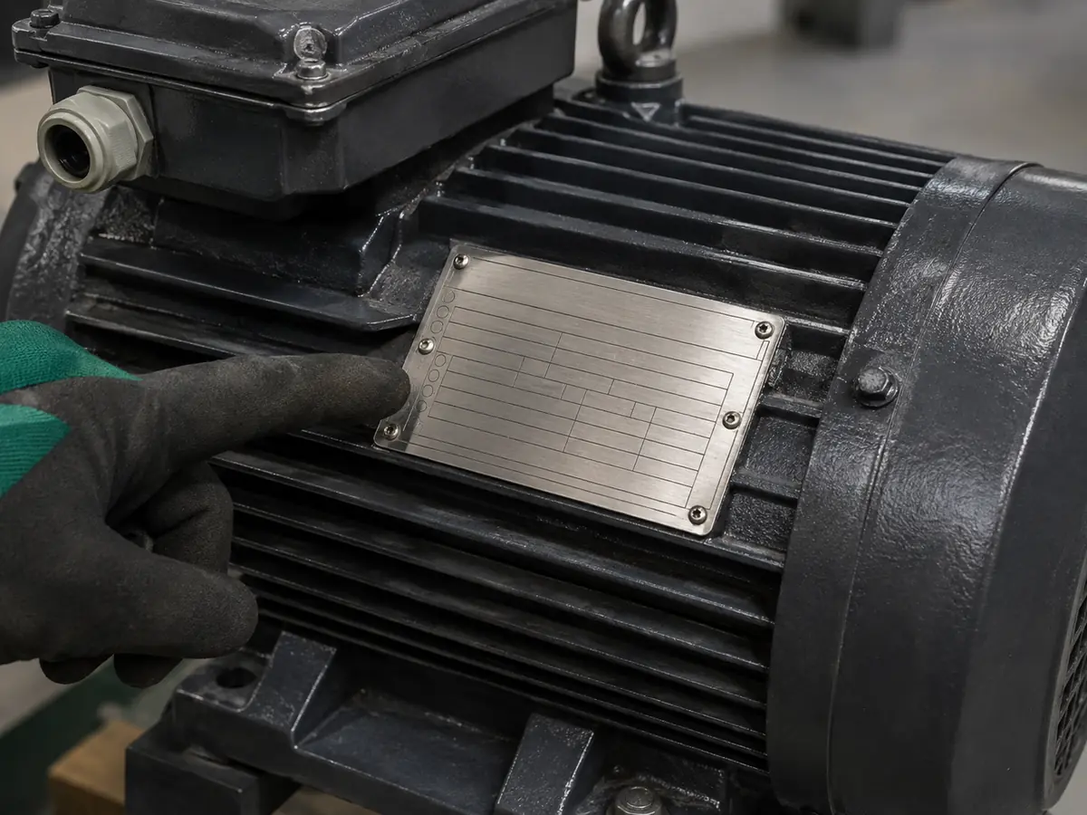
If some values are unclear, use the step-by-step guide on how to read a motor nameplate before requesting a final model.
3. Match the supply and motor voltage correctly
Confirm the actual input power at the installation site. State the nominal voltage, phase, and frequency. Also mention known voltage variation, weak-generator supply, transformer size, or long incoming cables. “Three phase” alone is not enough.
The VFD input voltage class must suit the supply. Its output must suit the motor connection and insulation. A drive does not normally raise its output voltage above the available input voltage. This becomes important when someone wants to run a higher-voltage motor from a lower-voltage supply or selects a motor connection without checking the plate diagram.
Single-phase input needs separate confirmation. Some drive ranges permit single-phase input with a three-phase output, often only within defined power limits or with derating. Never remove one input phase from a standard three-phase selection and assume the original current rating remains valid. Use the manufacturer’s approved input arrangement and sizing rule.
4. Size by continuous output current after derating
Once the voltage class is correct, compare the motor’s rated current with the drive’s continuous output current for the selected duty rating. The drive current must cover the application after any required derating. This is the point where a kW-only choice often fails.
Derating may apply because of high ambient temperature, altitude, switching frequency, enclosure design, input phase arrangement, or another condition stated in the drive manual. These factors differ by product series. Do not apply one brand’s derating table to another drive.
A simple current check
Take a loaded conveyor with a 15 kW, 400 V motor rated at 30.5 A. In the supplier’s heavy-duty table, the 15 kW drive can deliver 30 A; the next model can deliver 37 A. I would cross the 30 A option off the shortlist. It is already half an ampere below the motor rating before a hot cabinet, high altitude, or any other derating takes away more capacity. The 37 A model becomes the sensible candidate, although its overload curve and the rest of the application still need checking.
This example does not mean every 15 kW motor requires the same drive. Use the actual motor current, drive duty table, ambient conditions, and load profile.
5. Check overload as a current-and-time requirement
“Heavy duty” is not a universal number. One series may define normal duty and heavy duty with different current ratings and overload periods. Another may publish several overload classes. Read the exact table for the model under consideration.
An overload percentage means little without a clock beside it. Tell the supplier, for example, that a loaded start reaches about 140% current for eight seconds and occurs once every twenty minutes. That description can be checked against a drive curve. “Heavy load” cannot. A single breakaway surge after a long idle period is also very different from a mixer that bites into thick material every minute. The drive must clear the peak without reaching its current limit, and its thermal model must recover before the next one arrives.
Acceleration time changes the demand too. A high-inertia fan may not need high running torque, yet it can require a long ramp. A loaded conveyor may need strong torque immediately. If the requested acceleration is too short, the drive may reach its current limit before the motor reaches speed. Increasing drive size can help in some cases, but a more realistic ramp, correct control mode, or mechanical change may solve the actual problem.
6. Define the required speed range and low-speed torque
Write down the minimum continuous speed, normal operating speed, and maximum speed. Then state the torque needed at those points. Avoid a vague request such as “0 to 50 Hz.” A motor can rotate at a low frequency without being suitable for continuous loaded operation there.
Many uncomplicated pumps, fans, and conveyors run well with V/Hz control. When the load changes quickly or speed droop becomes noticeable, sensorless vector control often gives a firmer torque response without adding an encoder. Encoder feedback earns its extra wiring and commissioning work on applications that must hold speed closely, produce dependable torque near zero speed, or react sharply to a changing command. That points toward closed-loop vector control. Check the combination, though: the selected drive must support both the motor technology and the proposed feedback device.
Operation above the motor’s base frequency enters a field-weakening region. Available torque falls as speed rises, and the mechanical speed limits of the motor and driven machine still apply. Do not approve overspeed simply because the VFD can output a higher frequency.
7. Identify stopping and braking energy
A VFD can control deceleration only if the system has somewhere to send the returned energy. With a low-inertia load and a gentle stop, the drive may absorb or manage the energy without extra hardware. A fast stop, large flywheel, descending load, or overhauling conveyor can raise the DC-bus voltage quickly.
Depending on the duty, the design may need a braking chopper and resistor, a regenerative drive, a common DC bus, or a longer deceleration time. A mechanical holding brake serves a different purpose. It must not be treated as a substitute for electrical deceleration, and safety-critical hoisting requires a dedicated machine and risk assessment.
8. Check the motor, cable, and output side as one system
PWM drive output places different electrical stress on a motor than a sinusoidal mains supply. Motor insulation, cable length, grounding, carrier frequency, and installation quality all affect the result. Long motor cables can increase reflected-wave voltage at the motor terminals. They can also increase leakage current and EMC problems.
Ask for the distance from VFD to motor, cable type, grounding arrangement, and whether the drive will control one motor or several. The application may need an output reactor, dV/dt filter, sine-wave filter, insulated bearing, shaft-grounding measure, or an inverter-duty motor. Follow the drive and motor manufacturers’ limits. The U.S. Department of Energy also highlights cable length, filtering, motor insulation, grounding, and bearing-current risks in its guidance on motor and adjustable-speed drive performance.
A multi-motor arrangement needs its own review. The VFD must cover the combined motor current, while each motor normally needs suitable individual overload protection. If a motor can connect or disconnect while the drive runs, explain the switching sequence before selection.
9. Design for the cabinet and the real site
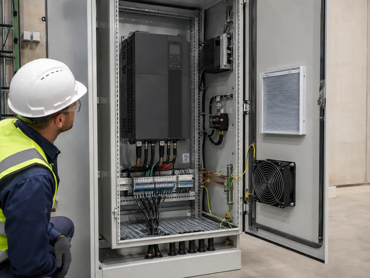
A drive can have comfortable current margin on paper and still lead a short life at the site. Put that same unit in a sealed cabinet beside a flour line, inside a damp pump house, or near metal dust that can conduct across a circuit board, and the risk changes. Give the supplier the highest expected cabinet temperature and the installation altitude, then describe moisture, dust, corrosive vapour, and vibration in ordinary language. Also say whether the drive sits indoors, outdoors, on a wall, or inside another enclosure. Those details determine derating and protection far more clearly than the phrase “industrial environment.”
Also decide whether the quoted item is an open drive or a complete panel. An IP20 drive installed inside a suitable cabinet is not the same deliverable as an IP55 or IP65 wall-mounted unit. The enclosure affects cooling, access, filters, gland plates, and maintenance. Cabinet heat calculations should include the VFD losses and other components, not the motor kW.
10. Confirm control, communication, EMC, and safety functions
Finish with the interfaces. List the start command source, speed reference, analogue signal type, digital inputs, relay outputs, feedback sensor, and communication protocol. State whether the machine needs local keypad control, remote terminals, PLC communication, PID control, sleep and wake functions, or automatic restart after a permitted power interruption.
Review EMC and harmonics at the system level. The required line reactor, DC choke, EMC filter, shielded cable, or harmonic solution depends on the supply, drive design, installation category, and local requirements. A specification that only says “with filter” leaves too much room for different interpretations.
Safety functions need the same precision. If the design uses Safe Torque Off, emergency stopping, a safety PLC, or external contactors, name the required function and the applicable machine risk assessment. Do not assume that a standard run/stop input creates a safety-rated stop.
A practical VFD inquiry checklist
Before asking for a final model and price, send the following information in one file. Photos are useful, but typed values help prevent reading errors.
- What is being driven? Name the actual machine and say whether it normally starts empty or loaded: pump, fan, conveyor, mixer, compressor, spindle, hoist, or something else.
- Which motor is fitted? Attach a readable plate photo and type out the voltage, phase, current, frequency, kW or hp, rpm, winding connection, and motor type.
- Power supply: voltage, phase, frequency, transformer or generator information, and known fluctuation.
- Duty: operating hours, starts per hour, overload level, overload duration, and repetition.
- Speed: minimum continuous, normal, and maximum speed, plus torque at low speed.
- Ramps: required acceleration and deceleration times.
- Braking: coast, ramp stop, fast stop, overhauling load, or regenerative operation.
- Installation: ambient temperature, altitude, enclosure, dust, moisture, vibration, and cabinet cooling.
- Output side: motor cable length, one or multiple motors, and any output filter.
- Control: keypad, terminals, analogue reference, PID, encoder, PLC, and communication protocol.
- Compliance: required documentation, EMC arrangement, safety function, and destination market.
When one item is unknown, mark it as unknown. That is better than filling the gap with an assumption. A supplier can then identify the open point before production rather than during commissioning.
Common VFD selection mistakes we would stop before approval
- Matching only the kW: the selected drive current sits below the motor nameplate current.
- Ignoring the duty column: the same model frame has different normal-duty and heavy-duty ratings.
- Calling every pump variable torque: centrifugal and positive-displacement pumps do not share the same torque pattern.
- Promising full torque at very low speed: the motor’s self-cooling cannot support the required continuous duty.
- Using a short deceleration time without an energy path: the drive trips on DC-bus overvoltage.
- Forgetting site derating: a high-temperature or high-altitude installation reduces the available output.
- Leaving cable length until installation: the motor later needs output protection that was absent from the quotation.
- Treating a run command as a safety function: the control design does not meet the machine’s safety requirement.
Make the final decision from the worst operating point
The best VFD choice is not always the largest drive, and it is rarely the cheapest matching kW. It is the model that can deliver the required current and torque through the real speed range, survive the site conditions, stop the load as intended, and communicate with the control system. It should do that without hiding unnecessary oversizing inside the quotation.
We prefer to mark every assumption during selection. If the load inertia is missing, we say so. If low-speed torque is critical, we ask how long the machine operates there. If the current rating sits close to a model boundary, we check the exact drive table rather than rounding down. This takes a little longer at the inquiry stage. It saves much more time when the cabinet reaches the site.
Next selection step
Compare the preliminary power range, then verify it with current and duty
Use the UFELE VFD power selection table for an initial frame-size reference. Final selection should still follow the motor current, load profile, overload demand, derating, and installation checks explained above.
Frequently asked questions
VFD selection FAQ
Six practical answers for the questions that usually appear between the first inquiry and final model approval.
Can I choose a VFD only from the motor kW or hp?
No. Use kW or hp for preliminary screening, then confirm motor full-load current, voltage, load type, speed range, overload duty, environment, and drive derating. The drive’s continuous output current must cover the application.
Should the VFD current be higher than the motor current?
The selected drive’s usable continuous output current should not be lower than the current required by the motor and load after applicable derating. A larger margin may be necessary for overloads or special duty, but arbitrary oversizing can add cost and affect protection or control. Follow the exact drive manual.
What is the difference between normal-duty and heavy-duty VFD ratings?
They usually represent different continuous-current and short-term overload capabilities for the same drive family. The percentages and time periods vary by manufacturer and series. Match the published duty rating to the machine’s current-versus-time profile.
Do pumps and fans always use a normal-duty VFD?
No. Centrifugal pumps and fans often behave as variable-torque loads, but the actual operating point, acceleration, process pressure, minimum speed, and possible blockage still matter. Positive-displacement pumps can behave as constant-torque loads and need a different review.
When does a VFD need a braking resistor?
A braking resistor may be needed when deceleration or an overhauling load returns more energy than the drive can manage through its normal DC bus. The answer depends on load inertia, speed, stopping time, repetition, and whether the drive includes or supports a braking chopper.
Does a long motor cable change VFD selection?
It can. Long cables can increase reflected-wave voltage, leakage current, and EMC concerns. The drive or motor may require an output reactor, dV/dt filter, sine-wave filter, different carrier-frequency setting, or other measures. Check the limits for the exact drive, motor, cable, and installation.