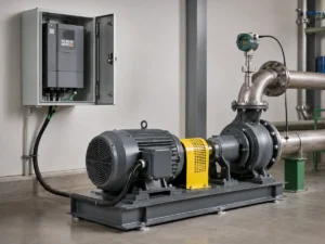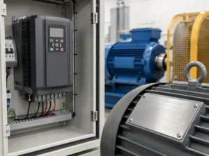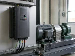
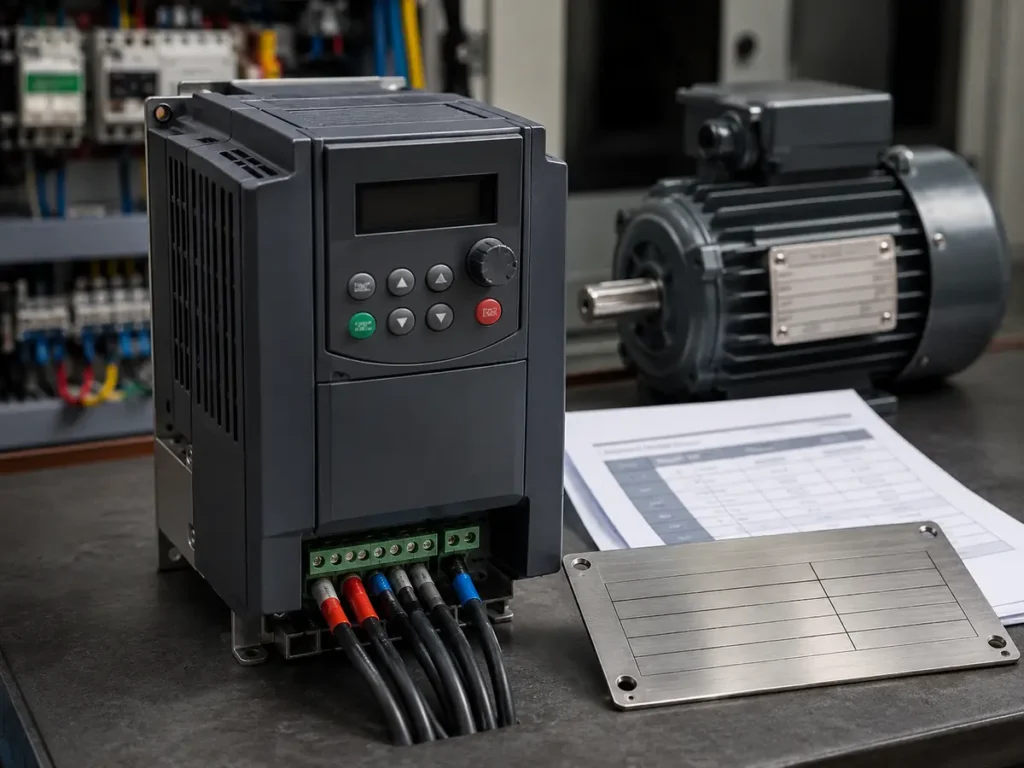
A VFD datasheet can look complete while leaving out the one condition that changes the selection. The serious work is not collecting more parameter names. It is checking whether the voltage, current, overload, control, braking, and environmental claims all belong to the same model and duty rating.
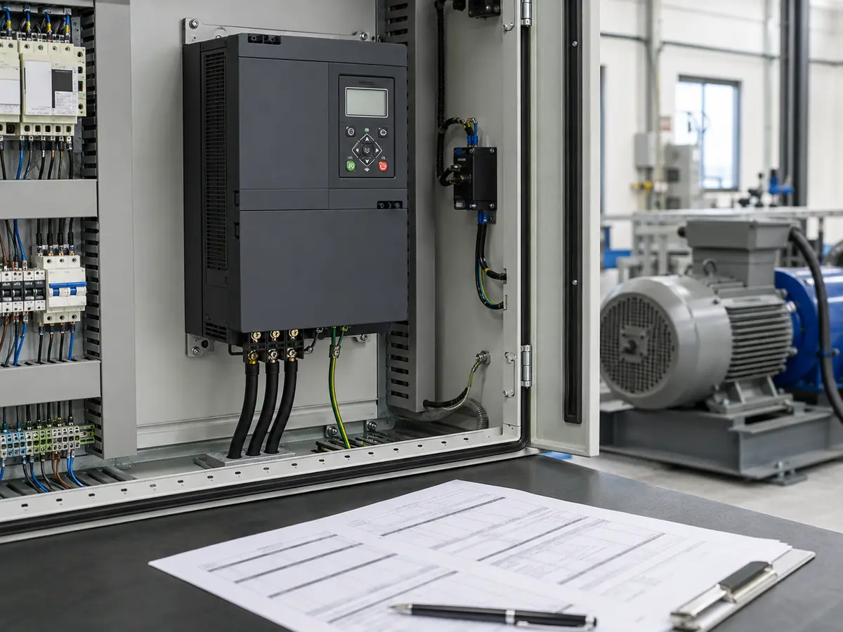
Which VFD parameters should a buyer check first?
Begin with the exact model code and its input voltage class. Then find the continuous output current in the correct normal-duty or heavy-duty column and compare it with the motor rated current. Check the overload value together with its duration and recovery condition. After that, review the control method, speed range, braking arrangement, I/O, communication, enclosure, ambient temperature, altitude, carrier-frequency derating, motor-cable limit, and EMC provisions. A parameter is useful only when its test or operating condition follows it.
A quotation may say “15 kW, 400 V, vector control” and still leave me unsure which drive is being offered. I have opened catalogues where one product name covers a low-voltage model, a 400 V model, two duty columns and more than one braking arrangement. An EMC suffix may change with the destination market as well. If the quotation stops at the family name, I circle that line and ask for the full model code plus the catalogue page used to prepare it.
This article stays on the drive side of the decision. Motor voltage, connection, and current still need to be settled first; our guide on how to read a motor nameplate covers that review. Load torque and operating duty also matter. If those are unknown, even a perfectly copied datasheet cannot complete the VFD selection.
Do not separate a rating from its model and conditions
The first page I distrust is the one that promises everything but identifies no exact model. “Up to 630 kW,” “200% starting torque,” and “built-in communication” may all be true somewhere in the product family. They may not be true together on the frame in the quotation. Small frames can include a braking unit that larger frames treat as an option. An IP20 cabinet unit and an IP65 wall-mounted version may also use different cooling and derating rules.
Keep the model code long enough to include its power, voltage, enclosure, keypad, braking, and regional suffixes. If the supplier shortens it on the proforma invoice, ask for a cross-reference. That small administrative point carries real site responsibility: the technician will install the model delivered, not the family described in a brochure.
| Parameter area | What the headline may omit | Evidence to keep with approval |
|---|---|---|
| Power and current | Normal-duty versus heavy-duty column | Exact model rating row and motor current |
| Overload | Duration, repetition, and starting condition | Overload curve or stated time profile |
| Control | Encoder need and motor-type limits | Control-mode table for the selected firmware |
| Braking | Chopper, resistor, and resistor duty are different items | Wiring diagram and resistor calculation |
| Environment | Temperature, altitude, carrier frequency, and enclosure derating | Installation manual and project conditions |
Input voltage, output voltage, power, and current must agree
I read the supply line before the motor kW. If the site note says 220 V and the offered model starts at 380 V, I stop there; no parameter setting repairs that mismatch. The reverse shortcut fails too. A drive built for a 200–240 V supply cannot be turned into a normal 400 V motor source through software. Once the voltage class agrees, I look at its permitted tolerance and the site supply quality. A weak generator can appear acceptable at rest, then dip far enough during acceleration to trip the drive.
On the output side, current usually settles arguments that kW begins. Compare the motor rated current at its actual connection with the drive’s continuous output current. Do this in the correct duty column and after known derating. The nearest kW line is a useful way to find the table row, not permission to ignore a current shortfall.
Quotation A may lead with kVA, quotation B with amperes, and quotation C with a recommended motor kW. Placing those three figures in one comparison cell hides rather than solves the difference. I return to continuous output current and the named duty column. It is quite possible for a model carrying a larger normal-duty kW label to receive a smaller heavy-duty motor recommendation because more overload reserve has been set aside. For centrifugal applications, the VFD for pumps guide explains why the load curve can allow a different duty choice than a loaded conveyor.
An overload percentage without time is unfinished information
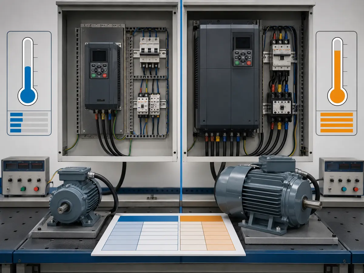
“150% overload” sounds reassuring until someone asks for how long. Ten seconds, sixty seconds, and a short starting boost are not the same promise. The manual may also restrict how often the overload can repeat or define it from the drive rated current rather than the motor current. That distinction matters when a conveyor restarts loaded or a mixer meets a dense batch.
Normal duty often serves variable-torque loads with modest overload demand. Heavy duty reserves more current for constant-torque or harder-starting machinery, sometimes reducing the stated motor kW for the same physical drive. The names are not universal across manufacturers. I compare the actual continuous current and overload profile instead of assuming every “HD” column means the same thing.
Acceleration time can turn an ordinary load into an overload problem. If the requested ramp is shorter than the motor and machine can manage with available torque, the drive may reach its current limit and extend the ramp or trip. Increasing the VFD frame can help only when the motor, supply, mechanics, and process allow the extra torque. It is not a substitute for understanding the inertia.
Control mode claims need a motor and speed requirement
For a pump or fan, plain V/f control may already do the required job. A loaded mixer that must remain steady at low speed sends the review in another direction. I may then consider sensorless vector control, but only after confirming that the correct motor data can be entered and that the site can perform the permitted autotune. When the process genuinely needs closer speed or torque feedback, an encoder and closed-loop vector mode enter the discussion. The longer control-mode name is not, by itself, a reason to buy it.
I look for the motor types supported by each mode. A three-phase induction motor, permanent-magnet motor, and synchronous-reluctance motor can require different algorithms and firmware options. Then I check the claimed speed-control range, speed accuracy, torque response, and starting torque under the stated control mode. A “200% torque at 0 Hz” line may depend on encoder feedback, a particular motor, or a short test condition.
Autotuning also deserves a practical note. Rotating tune may give better motor identification, but the machine may not be free to rotate during commissioning. Static tune can be easier on site yet provide different performance. The person approving the VFD should know which method the application permits before low-speed performance becomes a commissioning surprise.
Carrier frequency, motor noise, heat, and braking are linked
A higher carrier frequency can reduce audible motor noise. It can also increase switching losses and heat inside the drive. The manual may require output-current derating as carrier frequency rises, especially at high ambient temperature. If a quotation highlights quiet operation but keeps the maximum current from the lowest carrier-frequency condition, I ask for the applicable derating curve.
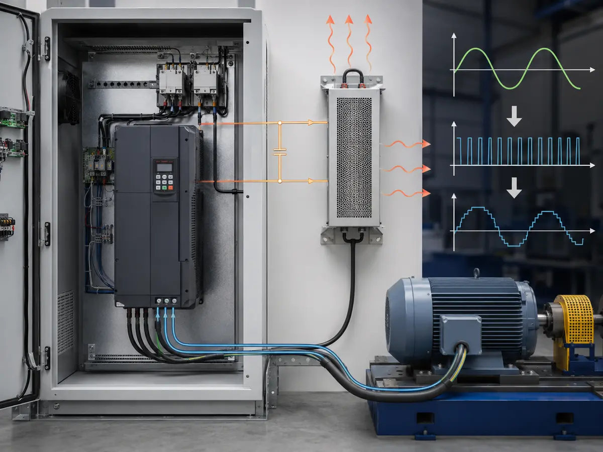
Long motor cables add another concern. Fast output pulses can increase reflected voltage at the motor terminals and place more stress on insulation. Cable capacitance can also increase drive current. The solution may involve a lower carrier frequency, output reactor, dV/dt filter, sine-wave filter, suitable motor cable, or an inverter-duty motor. The correct choice depends on voltage, cable length, motor insulation, switching frequency, and installation rules.
Braking language is frequently shortened too far. An internal braking chopper controls energy sent to an external resistor; it is not the resistor itself. The resistor must have suitable resistance, power, thermal protection, and duty for the stopping cycle. Some applications instead need a regenerative unit or a longer deceleration time. A heavy load cannot be stopped safely just because the keypad accepts a three-second ramp.
Count functions, not only terminals
Three digital inputs do not tell me whether the required run, reverse, fault reset, multi-speed, jog, and external trip commands can all be assigned at once. Check the function list, input logic, common terminals, and whether the PLC uses source or sink wiring. A terminal marked AI may accept 0–10 V, 4–20 mA, or both, but the selection can require a jumper, parameter, or different common.
Analog output accuracy matters when it feeds a remote display or control system. Relay contacts need their voltage and current rating checked against the device they switch. Pulse inputs, high-speed outputs, STO terminals, thermistor inputs, and encoder interfaces may be standard, optional, or unavailable on the selected frame.
“RS485 included” is one of those lines that looks settled until the controls engineer asks for the register list. I still need the protocol—often Modbus RTU—together with baud rate, parity, addressing and word order. The PLC programmer also needs the right register map. If a card is required, its code belongs beside the VFD model on the order. I apply the same rule to Ethernet, PROFINET, EtherNet/IP and CANopen: identify the actual option and compatible firmware while the quotation is open, not after an email promise has been separated from the purchase file.
The installation can reduce a correct paper rating
Most rating tables assume a stated ambient temperature, altitude, mounting clearance, and cooling path. Above that altitude or temperature, the drive may need derating, and side-by-side mounting can alter the clearance rule. A site once described as “40 °C ambient” still leaves an important blank: is that the room temperature or the air around the drive after the cabinet doors close? Reactors, contactors and braking resistors add their own heat, so the internal value can be considerably higher.
I treat IP20, IP54 and IP65 as enclosure information, not as a cooling decision. A sealed unit still has heat to release. Dust may be conductive, humidity may become condensation, and corrosive gas or vibration may make an otherwise ordinary cabinet unsuitable. Direct sun adds another load outdoors. When the VFD is mounted inside a larger cabinet, that complete assembly—airflow, filters, clearances and heat removal—is the installation I review.
EMC compliance also belongs to a system. An internal filter may cover a defined supply network, cable length, carrier frequency, and installation category. Shield termination, grounding, line reactors, RFI filters, motor cable, and separation from signal wiring still matter. Ask which standard and environment the declaration covers, and keep the installation instructions with the project file.
Illustrative review: a 15 kW conveyor offer
Suppose the motor file shows 400 V, 29.5 A, 50 Hz, and a loaded conveyor. One supplier offers a drive row marked 15 kW heavy duty, 32 A continuous, and 150% overload for 60 seconds. The ambient limit is 40 °C at the default carrier frequency, while the proposed cabinet is expected to reach 45 °C. The motor cable is 80 m, and the machine must stop in eight seconds.
The 32 A row clears the motor’s 29.5 A on paper, but the review is not finished. I need the 45 °C derating value and the carrier frequency planned for site. I also want the cable-length guidance and any output-reactor recommendation. For the stop, the mechanical inertia and braking cycle decide whether an internal chopper and external resistor are enough. The 150% overload line helps with acceleration only if its duration and repetition fit the actual cycle.
| Review item | Illustrative data | Open point before approval |
|---|---|---|
| Motor and output current | 29.5 A motor; 32 A VFD heavy-duty rating | Continuous current after 45 °C and carrier-frequency derating |
| Overload | 150% for 60 seconds | Acceleration demand, repetition, and current-limit behaviour |
| Motor cable | 80 m | Permitted length and need for output reactor or filter |
| Stopping | Eight-second deceleration | Inertia, regenerated energy, chopper, resistor, and thermal duty |
| Cabinet | 45 °C expected internal temperature | Ventilation, spacing, total heat loss, and final derating |
This example is a review method, not a recommendation for every 15 kW conveyor. A different load cycle, cable, altitude, supply, or cabinet can change the answer. The responsible conclusion may be a larger frame, a different braking arrangement, more cooling, or simply a longer ramp.
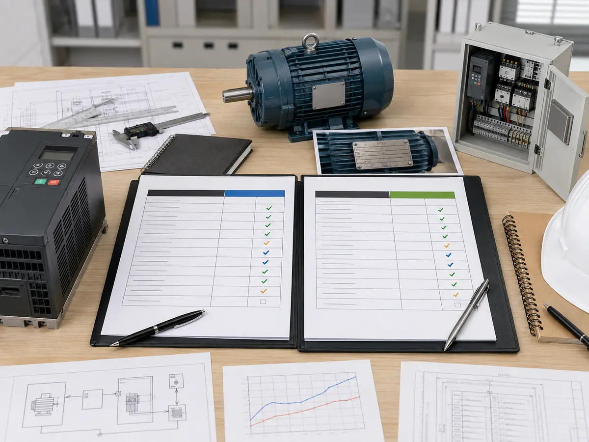
What should go into the approval and quotation file?
A useful request starts with evidence: a readable motor plate, the machine it drives and the actual supply voltage and frequency. I then add what the machine must do—normal load, starting condition, speed range, ramp times and starts per hour. Ambient temperature, altitude, enclosure and motor-cable length prevent the supplier from assuming an easy installation that does not exist.
The remaining details depend on the control scheme. I note the required signals and protocol, the braking duty and the EMC expectation, then call out any encoder, thermistor, bypass, reactor, filter or safety function already in the design. In return, I expect a complete model code tied to a duty class, continuous current and overload profile. The reply should also identify the control mode, braking hardware, included and optional I/O, communication option, enclosure, heat loss, derating limits and manual revision. If two suppliers have worked from different assumptions, I leave those differences visible rather than squeezing both offers into the same kW price cell.
VFD datasheet approval check
- Exact model and suffixes appear on the quotation and datasheet
- Input class agrees with the real site supply
- Output current covers the motor after all applicable derating
- Duty column and overload time match the load cycle
- Control mode supports the motor and required speed performance
- Carrier frequency, cable length, braking, and motor insulation are reviewed together
- I/O and communication functions can operate simultaneously as required
- Ambient, altitude, enclosure, cooling, EMC, and approvals are documented
UFELE supplies variable frequency drives for pumps, fans, conveyors, machinery, and other motor-control duties. Use our VFD power selection table for an initial model comparison, then send the complete duty file through the contact page. We will check where a parameter needs a condition before treating it as an approved rating.
Frequently asked questions
Which VFD parameter is most important for sizing?
Continuous output current in the correct duty class is central, but it must be checked after environmental and carrier-frequency derating and against the motor current and load cycle.
What is the difference between normal duty and heavy duty?
They usually provide different continuous current, motor kW, and overload capability from the same drive family. Definitions vary, so compare the actual rating and overload tables.
Does 150% overload mean the VFD can run continuously at 150% current?
No. The percentage must be read with its permitted duration, repetition, thermal condition, and rating basis.
Does a built-in braking unit include the braking resistor?
Not necessarily. A built-in chopper may control an external resistor, which still needs a resistance, power, thermal, and duty-cycle calculation.
Why does carrier frequency affect VFD current?
Higher carrier frequency can increase switching loss and heat. The manufacturer may require output-current derating, especially at higher ambient temperatures.
Is RS485 enough information for PLC communication?
No. Confirm the protocol, baud rate, parity, address, register map, wiring, word order, and any required communication option or firmware.