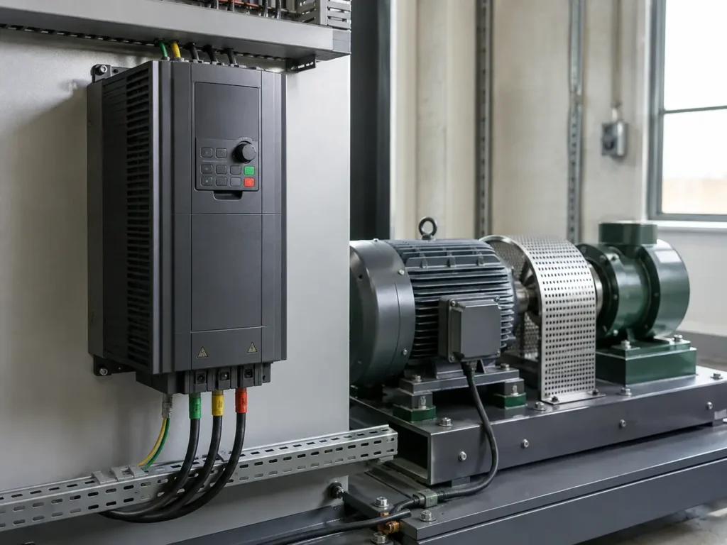
A VFD is a variable frequency drive, a type of motor controller used to control the speed of the motor rather than leave it running at full speed. It first converts fixed-frequency AC power to DC. It then uses solid-state switches to build the frequency and voltage that the AC motor needs. The control section corrects that output many times each second.
How does a VFD work?
A VFD receives AC power at a fixed voltage and frequency. A rectifier changes that AC to DC. Capacitors and, in some designs, a choke stabilize the DC bus. An inverter stage then switches the DC through six power devices, usually IGBTs, to create a pulse-width-modulated output. By changing the switching pattern, the drive controls the fundamental frequency and effective voltage applied to the motor. Its processor also watches current, speed estimates, feedback signals, and protection limits.
This sequence explains why a VFD is called a variable frequency drive. You may also see variable speed drive, an adjustable speed drive, or adjustable frequency drive in specifications. The terms can overlap, although not every adjustable-speed technology uses the same power circuit. Inside a modern VFD, changing the display frequency is only one part of the job. The drive coordinates voltage, current, and frequency so the motor can produce useful torque while following an acceleration ramp or process command.
If you first need the basic definition, common applications, and limits, read What Is a Variable Frequency Drive? This guide starts inside the power converter and follows energy toward the motor.
The three-stage power path inside a VFD
Most low-voltage voltage-source VFDs use the same broad layout. Manufacturers may change the input circuit, DC-link components, solid state switching devices, cooling system, and control method. Even so, the familiar rectifier–DC bus–inverter path remains the clearest way to see how a variable frequency drive works.
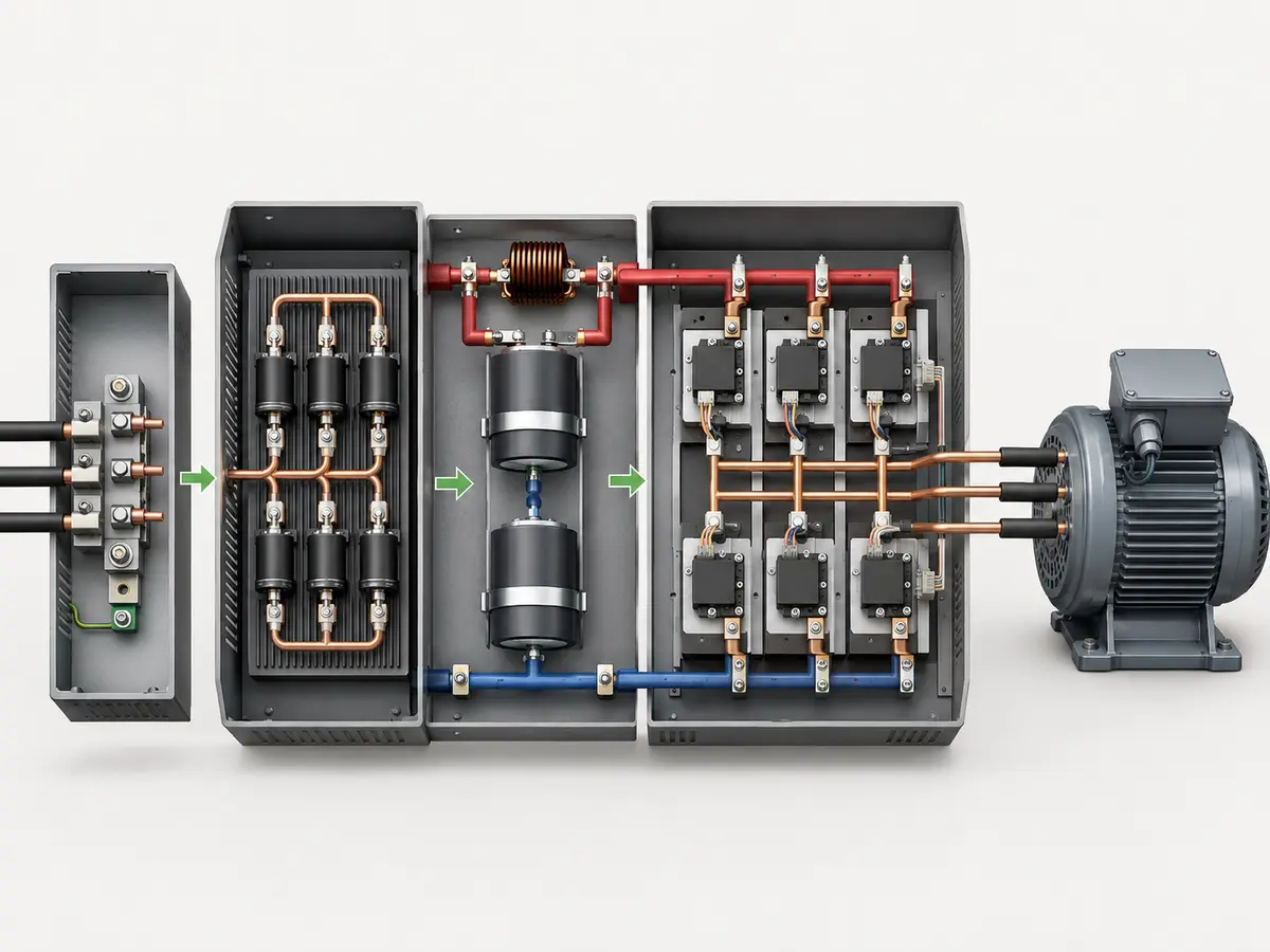
| Stage | What enters | What the stage does | What leaves |
|---|---|---|---|
| Rectifier | Fixed-frequency AC supply | Allows current to charge the DC link with one polarity | Pulsating DC power |
| DC bus | Rectified power | Stores energy and reduces DC-voltage ripple | A more stable DC source |
| Inverter | DC-bus power | Switches each motor phase in a controlled pattern | Variable-frequency PWM output |
The control board sits beside this power path. It receives the run command and speed reference. It reads internal voltage and current measurements. It may also receive a pressure signal, encoder feedback, PLC data, or a digital command. Its software turns those inputs into gate signals for the power switches.
Stage 1: the rectifier converts incoming AC to DC
A common three-phase drive uses a six-pulse diode bridge at its input. The conducting diode pair changes as the three supply phases rise and fall. Current always reaches the positive and negative sides of the DC link with the same polarity. The result is DC with ripple, not a perfectly flat battery-like source.
Small drives designed for single-phase input can use a four-diode bridge. That does not mean any three-phase-input drive may be placed on a single-phase supply. The input current, ripple, rectifier loading, capacitor heating, and rated output can change sharply. The exact drive manual must approve the connection and any derating.
A basic diode rectifier allows power to move from the supply into the DC bus. It does not normally return sustained braking energy to the grid. Regenerative drives use a different input stage, often an active front end, when four-quadrant energy flow or tighter input performance is required.
Stage 2: the DC bus stores and smooths energy
The DC bus, also called the DC link or intermediate circuit, sits between the rectifier and inverter. Electrolytic capacitors commonly provide energy storage and reduce voltage ripple. Many designs also include a DC choke or another inductive element. The component mix depends on drive size and topology.
The capacitors do more than make the diagram look tidy. The inverter demands short bursts of current as it switches. The DC link supplies those bursts without asking the line for an identical instant-by- instant waveform. It acts as an electrical buffer between the input and output stages.
When a drive first receives power, an empty capacitor bank can draw a very large charging current. A precharge circuit limits that inrush. After the DC voltage reaches a suitable level, a relay or contactor may bypass the precharge resistance. Repeatedly cycling input power faster than the manual allows can overheat or damage this circuit.
The DC link also reveals what the motor is doing with energy. During normal motoring, power moves from the supply through the drive to the shaft. During a fast stop or an overhauling load, the motor can act as a generator. Energy then returns through the inverter and raises the DC-bus voltage. The drive must slow the deceleration, dissipate the energy, or send it elsewhere.
Stage 3: the IGBT inverter creates a new output
The inverter stage usually contains three switching legs, one for each motor phase. Each leg has an upper and lower power switch. In a low-voltage industrial drive, that switch is commonly an insulated gate bipolar transistor (IGBT). Other semiconductor technologies and multilevel topologies also exist, especially at different power and voltage levels.
The controller never treats the upper and lower device in one leg as an ordinary pair of light switches. Turning both on together would short the DC bus. Gate-driver timing therefore inserts a small dead time and enforces a safe switching sequence. Protection circuits also watch for overcurrent, gate faults, excessive temperature, and abnormal DC-bus conditions.
By selecting which switches conduct, the inverter connects each motor terminal toward the positive or negative side of the DC bus. The individual terminal voltage jumps rapidly. Across the three phases, the timed pulse pattern creates a rotating fundamental voltage system. That fundamental component produces motor flux and torque.
How pulse-width modulation builds frequency and voltage
Pulse width modulation (PWM) controls the duration and placement of the inverter pulses. Think of the switch as fully on or fully off. The controller does not hold an IGBT halfway open to draw a smooth sine wave. Instead, it changes how long each pulse remains in one state. The resulting average over short intervals follows the intended waveform.
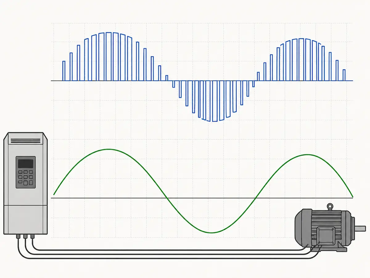
Two frequencies must not be confused. The output fundamental frequency sets the rotating-field speed. The carrier or switching frequency tells the IGBTs how often to change state. A drive might command a 35 Hz fundamental while its power devices switch thousands of times per second.
A higher carrier frequency can reduce audible motor noise and make current appear smoother. It also increases switching losses and drive heating. The allowed output current may fall at higher carrier settings. Long cables, filters, motor type, acoustic needs, and ambient temperature all influence a sensible setting. The highest number in the parameter menu is not automatically the best choice.
The U.S. Department of Energy describes modern PWM VFDs as drives that rectify fixed-frequency AC to DC and use an inverter to create an adjustable-frequency, variable-voltage output. Its guide on premium-efficiency motor selection and application also discusses IGBT switching and motor-drive interaction.
How output frequency, voltage, and current control the motor
For an AC motor, electrical frequency sets the speed of the rotating magnetic field. Varying the frequency therefore changes that field speed, while the drive manages frequency and voltage together to preserve usable motor flux. The synchronous speed follows this relationship:
Synchronous speed
Ns = 120f / P, where Ns is synchronous speed in rpm, f is the fundamental frequency in hertz, and P is the number of motor poles.
A four-pole motor has a 1,500 rpm synchronous speed at 50 Hz. At 35 Hz, that value becomes 1,050 rpm. An induction motor runs somewhat below synchronous speed because it needs slip to produce torque. The actual shaft speed therefore depends on load and the drive’s control method.
Reducing frequency without coordinating voltage can push the motor flux too high. A simple scalar drive therefore follows a voltage-to- frequency pattern below base speed. In the constant-flux region, this approach supports approximately constant torque within the motor and drive limits. Low-frequency voltage boost may compensate for stator resistance, but too much boost can raise current and heat.
Load behaviour matters here. A conveyor or mixer may need nearly constant torque across much of its speed range. Fans and centrifugal pumps are usually variable torque loads, so the torque demand falls sharply as speed drops. The VFD controls the motor output, but the driven equipment decides how much torque and power the shaft must deliver at each operating point.
Above base frequency, the drive usually cannot keep increasing output voltage because the available DC-bus voltage sets a ceiling. Frequency can rise while voltage stays near its limit. Motor flux then weakens, and the available torque falls. This is the field-weakening or constant-power region. Motor mechanical speed, bearings, balance, driven equipment, and required torque all need approval before overspeed operation.
Current relates closely to torque, but the relationship is not as simple as “more amps means more speed.” The control algorithm must establish magnetizing flux and produce the torque required by the load. A stalled conveyor can draw high current at zero speed. An unloaded motor can rotate near its commanded speed with much lower torque current.
How the Controller Responds to a Speed Command
The power section can switch only when the control section tells it what to do. A keypad setting, analog signal, PLC word, fieldbus command, preset speed, or PID loop first provides a reference. Ramp logic then decides how quickly that reference may change. The motor control algorithm calculates the voltage pattern or torque-producing current needed at that instant.
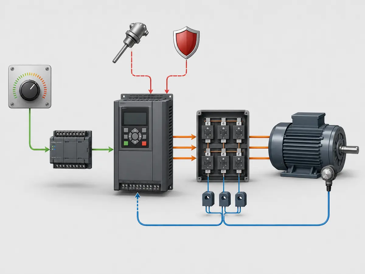
V/F Control vs Vector Control
V/F control follows a set relationship between voltage and frequency. It suits many pumps, fans, and simple machines. Vector control uses motor data and measured current to estimate torque and flux. It gives a stronger response when the load changes or the motor runs slowly.
| Control method | How it works | Where it fits |
|---|---|---|
| Scalar V/f | Follows a voltage-versus-frequency relationship | Simple pumps, fans, and non-demanding speed control |
| Sensorless vector | Uses a motor model and measured current without an encoder | Stronger torque response and speed regulation for many machines |
| Closed-loop vector | Adds encoder or resolver feedback to the control loop | Tight speed accuracy, low-speed torque, and dynamic loads |
| Direct torque control | Controls estimated motor torque and flux directly | Applications needing fast torque response, where supported |
Motor nameplate entry and identification matter most as control becomes more sophisticated. Rated voltage, current, frequency, speed, power, and motor type help the model estimate flux, slip, and torque. An autotune or identification run measures additional characteristics. Incorrect data can make a capable control mode perform poorly.
Process control adds another loop around motor control. For a pump, a pressure transmitter reports the actual pressure. The drive’s PID function compares that value with the setpoint and changes the speed reference. Motor current control still runs much faster underneath. The pressure loop asks for more or less speed; it does not switch the IGBTs directly.
This is why VFD controls can do more than accept a speed number from a keypad. In process control, the command may come from pressure, flow, temperature, level, or a PLC recipe. The drive still controls the speed of the motor, while the outer loop decides what speed the process needs at that moment.
ABB’s technical guide to direct torque control traces the development from scalar V/f control through PWM vector methods to direct torque control. It is a useful reminder that two drives can share the same rectifier–DC-link–inverter outline while using different control calculations.
What Happens During Acceleration?
When the operator presses Run, the drive raises its frequency command along the set ramp. It also raises voltage and watches motor current. If the load needs more torque than the current limit allows, the drive may hold or extend the ramp. A loaded conveyor often needs a longer ramp or more starting torque than a lightly loaded fan.
What Happens During Deceleration and Braking?
A stop command can produce several very different actions. The drive may stop switching and let the load coast. It may reduce the output frequency along a ramp. It may inject DC for a limited time where the drive and motor allow it. Or it may actively manage regenerative energy through a braking resistor or regenerative input stage.
During a controlled deceleration, the commanded rotating field can move below the actual rotor speed. The motor then develops braking torque and sends electrical energy toward the DC link. A high- inertia fan, centrifuge, downhill conveyor, hoist, or rapid machine cycle can return significant energy.
A braking transistor and resistor convert that energy to heat. The resistor needs the correct resistance, peak power, duty cycle, enclosure, and thermal protection. A regenerative unit can return energy to the supply, subject to the equipment and grid interface. If neither path is available, the drive must extend the stop time or trip on DC-bus overvoltage.
Why the real input and output waveforms matter
The VFD separates input frequency from output frequency, but it does not make every electrical effect disappear. The input rectifier can introduce harmonic current and contribute to voltage distortion in a weak system. The output inverter produces steep-edged voltage pulses. Each side therefore needs its own review.
- Motor insulation: long cables and fast voltage edges can produce reflected-wave peaks at the motor terminals. Motor insulation, cable length, rise time, and filters matter.
- Bearing current: common-mode voltage can contribute to shaft voltage and bearing discharge. Grounding, cable construction, filters, insulated bearings, or shaft grounding may be part of the solution.
- Electromagnetic compatibility: motor cable routing, shielding, bonding, control-wire separation, and filter installation affect interference.
- Motor heat: PWM adds some motor loss. A shaft-mounted fan also moves less cooling air at low speed. Continuous low-speed torque needs a thermal check.
- Output switching: contactors should not open and close routinely between a running VFD and motor unless the drive manufacturer and control sequence specifically allow it.
- Output capacitors: ordinary power-factor correction capacitors do not belong on the PWM motor output. Filters designed for VFD service follow different rules.
These effects do not mean a VFD is unreliable. They explain why a correct installation includes the motor, cable, grounding, enclosure, switching devices, and process duty. A drive can control the motor well only when the surrounding system supports it.
Example: what happens at a 35 Hz command?
Consider a standard four-pole induction motor rated for a 400 V, 50 Hz supply. Assume the application remains below base speed and uses an ordinary scalar V/f mode. The operator enters a 35 Hz speed command and presses Run.
1. The DC bus charges
The input rectifier conducts from the three-phase supply. The precharge path limits the initial capacitor current. When the DC link reaches its ready condition, the drive can enable the inverter.
2. The ramp moves toward 35 Hz
The controller does not usually jump from zero to 35 Hz. It increases the reference along the programmed acceleration ramp. Current limiting can hold or adjust that ramp if the machine asks for more torque than the allowed current can support.
3. PWM creates the motor output
The IGBTs switch the DC-bus voltage across the three output legs. Pulse widths change through each electrical cycle. The fundamental component rises toward 35 Hz while the effective voltage follows the selected V/f curve. The terminal voltage still consists of fast pulses.
4. The motor settles below 1,050 rpm
At 35 Hz, the four-pole synchronous speed is 1,050 rpm. The loaded induction motor settles somewhat below that value because it needs slip. A vector mode may estimate and compensate for slip more accurately than open-loop scalar control.
5. The drive keeps correcting
The processor continues reading current and internal conditions. It changes the switching commands when the load varies. If the application uses encoder or process feedback, that signal also changes the reference or torque calculation.
This example also shows why the display frequency is not guaranteed shaft speed. A direct 35-to-rpm conversion gives synchronous speed, not the exact rotor speed. Motor slip, load torque, motor data, control mode, current limits, and feedback determine what happens at the shaft.
How working theory changes VFD selection
Knowing how a VFD works helps a buyer ask better questions. The rectifier makes the supply phase and harmonic environment relevant. The DC bus makes braking energy and power-cycling frequency relevant. The inverter makes output current, motor-cable length, carrier frequency, and filter requirements relevant. The control algorithm makes motor data, low-speed torque, feedback, and tuning relevant.
The same power-conversion principle appears across industrial and commercial applications, from conveyors and machine tools to HVAC fans and water pumps. The label variable speed drive alone does not confirm suitability. Selection still starts with the AC motor, the driven equipment, the required torque profile, and the way the machine must start and stop.
Do not select the drive from motor kW alone. Record the supply voltage and phase, motor full-load current, load type, starting torque, speed range, stopping time, duty cycle, ambient temperature, altitude, cable length, control signals, and communication needs. Our guide on how to choose a VFD arranges those checks in a practical order.
When you are ready to compare voltage classes, power ranges, and functions, review the UFELE variable frequency drive range. The final drive, motor, protective devices, cabinet, wiring, machine sequence, and safety functions still need approval as one system.
Move from principle to a real application
Send the motor plate and describe what the machine must do
UFELE can review the voltage class, output current, load duty, speed range, braking need, control method, installation conditions, and required I/O before quotation. Clear operating details lead to a more useful first recommendation.
Contact UFELE about a VFD application
How a VFD Works FAQ
Short answers about VFD power conversion
These answers describe a common low-voltage PWM drive. Always use the exact product manual for installation, parameters, and safety.
Does a VFD change both frequency and voltage?
Yes. A VFD changes the fundamental output frequency to control the rotating-field speed. It also manages effective output voltage and current so the motor can maintain suitable flux and produce torque within the drive and motor limits.
Why does a VFD convert AC to DC first?
The DC link separates the fixed-frequency input from the adjustable output. It stores energy and gives the inverter a DC source that can be switched into a new three-phase pattern with the required frequency and effective voltage.
Is the output of a VFD a sine wave?
A standard PWM VFD does not produce a smooth utility-style voltage sine wave at its motor terminals. It produces fast voltage pulses. Their fundamental component drives the motor, while motor inductance makes the current smoother than the terminal voltage.
How do IGBTs control motor speed?
IGBTs switch the DC-bus voltage across three output legs. The controller changes each pulse’s timing and width. This creates an adjustable fundamental frequency and voltage pattern, which changes the motor’s rotating magnetic field and operating speed.
Does the hertz display equal the motor rpm?
No. Frequency sets synchronous speed according to motor pole count. An induction motor runs below synchronous speed because it needs slip to produce torque. Load, motor data, control mode, and feedback determine the actual shaft rpm.
Where does the energy go when a VFD stops a motor?
A coasting load loses energy through mechanical losses. During controlled regenerative braking, energy can return to the DC bus. The drive may extend the stop, send energy to a braking resistor, or return it to the supply through a regenerative front end, depending on the system.