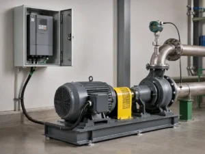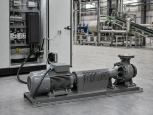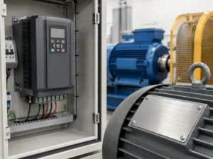
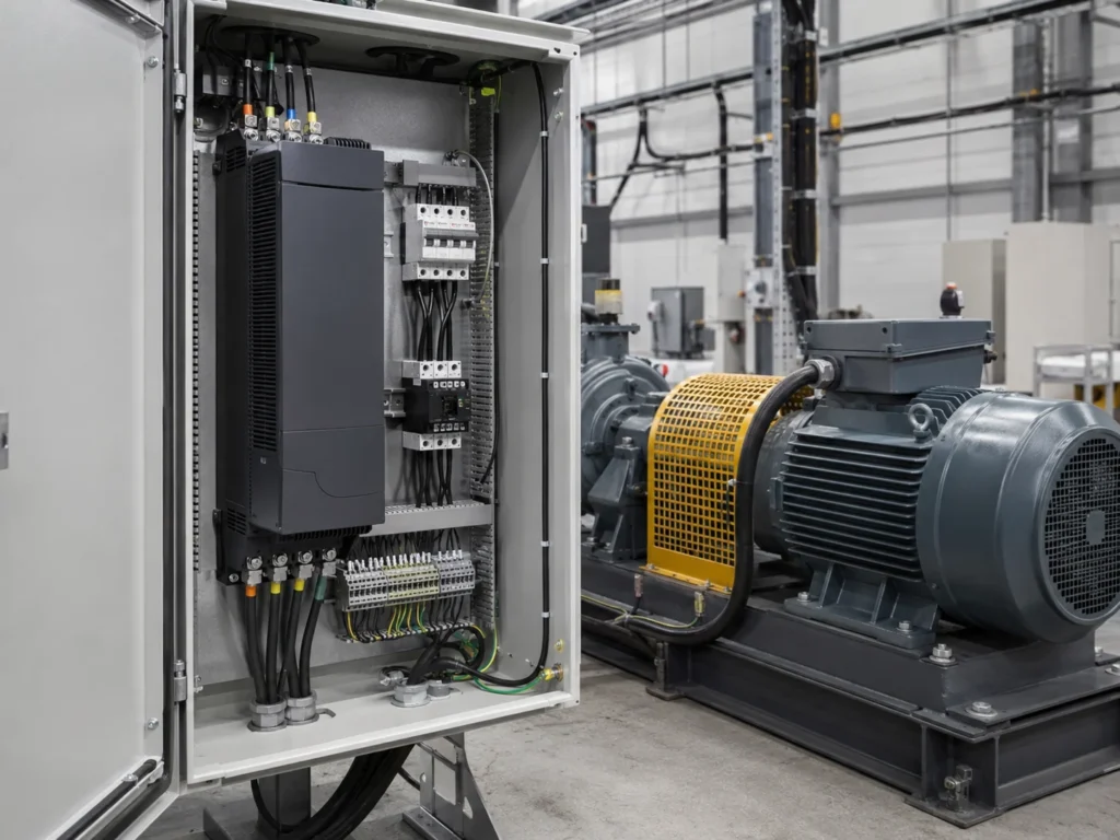
A variable frequency drive, or VFD, is an electronic controller that changes the frequency and voltage supplied to an AC motor. That simple description hides its real value. A VFD lets the machine use the speed the process needs instead of forcing the motor to run at one line-frequency speed whenever it is switched on.
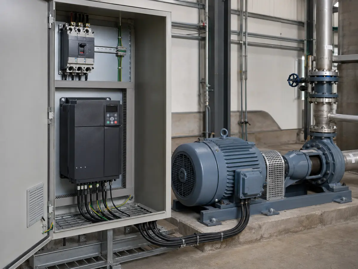
What is a variable frequency drive?
A variable frequency drive is a solid-state power electronic device used to control an AC motor. It receives electrical power at a fixed supply frequency, processes that power, and sends the motor an output with adjustable frequency and voltage. Changing the output frequency changes the motor’s operating speed. The drive can also manage acceleration, deceleration, torque response, direction, current limits, and signals from a PLC or sensor.
The easiest way to understand a VFD is to look at a machine that does not need one. Imagine a small workshop fan that only has two useful states: off and full speed. A direct starter may be all it needs. Now put a similar motor on an air-handling system where the required airflow changes all day. Running at full speed and closing a damper wastes part of the motor’s work. A VFD lets the fan slow down when the building needs less air.
What does VFD stand for?
VFD stands for variable frequency drive. “Variable” means the motor does not have to stay at one commanded speed. “Frequency” names the electrical quantity the drive changes. “Drive” is the equipment that controls the motor and its connected load.
You may also see AC drive, adjustable-frequency drive, inverter drive, variable-speed drive, or simply inverter. People often use these names loosely. In strict terms, variable-speed drive is the broader category because speed can be varied by electrical, mechanical, or hydraulic methods. A VFD specifically controls an AC motor by changing electrical frequency. Product terminology still varies by market, so a quotation should identify the motor, input supply, output rating, and application rather than rely on one label.
Why frequency changes AC motor speed
An AC motor connected directly to a 50 Hz or 60 Hz supply runs near a speed set by the supply frequency and the motor’s number of poles. The rotating magnetic field has a synchronous speed that can be estimated with a familiar relationship:
Synchronous speed
Ns = 120f / P, where Ns is synchronous speed in revolutions per minute, f is electrical frequency in hertz, and P is the number of motor poles.
A four-pole motor has a synchronous speed of 1,500 rpm at 50 Hz. At 40 Hz, the synchronous speed becomes 1,200 rpm. An induction motor’s shaft runs slightly below synchronous speed because it needs slip to produce torque. The nameplate may therefore show a rated speed such as 1,470 rpm rather than 1,500 rpm.
Frequency alone is not the whole control job. The drive also adjusts output voltage and manages current so the motor can produce useful torque without excessive magnetic flux or overheating. Modern control modes use motor data and current measurements to improve torque response and speed regulation. The right mode depends on the motor, load, required speed range, and performance target.
A VFD does not magically turn every standard motor into a precision positioning system. The actual shaft speed changes with slip, load, control method, tuning, and whether the system uses encoder feedback. For a pump or ventilation fan, sensorless control may be more than adequate. A hoist, winder, test stand, or machine tool can demand a much tighter review.
What sits inside a VFD
Most low-voltage VFDs move power through three stages: AC supply → rectifier → DC bus → IGBT inverter → variable-frequency output → AC motor. The rectifier converts AC to DC. The DC bus smooths and stores energy. The inverter switches that energy to create the motor output.
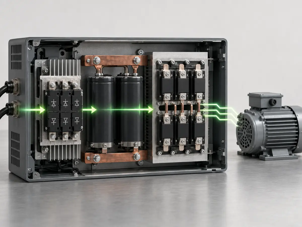
A standard drive uses fast voltage pulses rather than a utility-style sine wave at its output. Motor inductance smooths the current, while the controller manages frequency, voltage, and torque response. Cable length, grounding, motor insulation, and filters still matter.
For a step-by-step explanation of rectification, DC-bus energy storage, IGBT switching, and PWM output, read the VFD working principle.
The VFD is one part of a drive system
Catalogue photographs make the VFD look like a self-contained answer. At site, it works as one part of a larger system. The power source, protective devices, drive, motor cable, motor, driven machine, sensors, controls, enclosure, and operating sequence all affect the result.
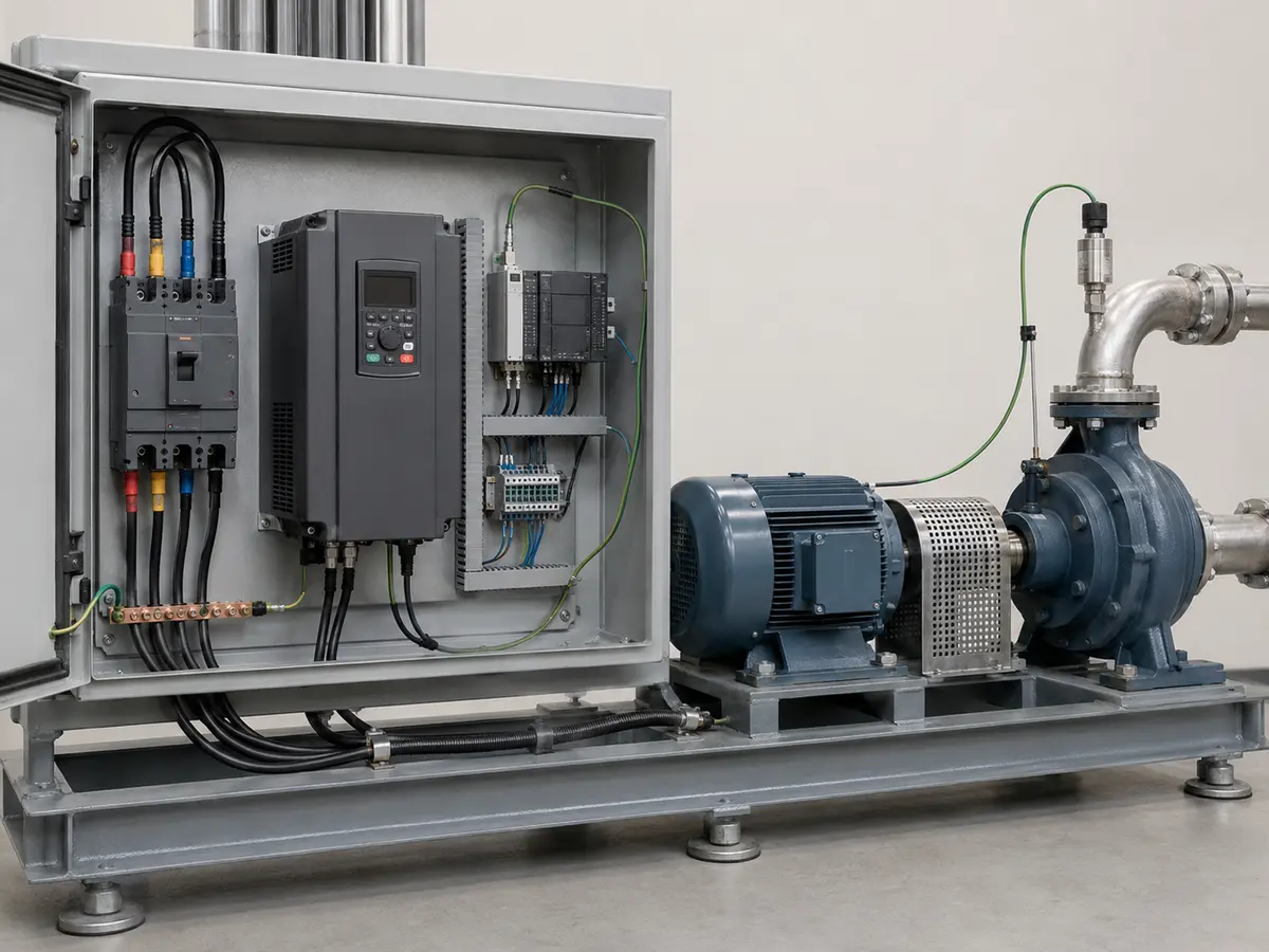
Consider the motor cable. A short run inside a machine may cause few difficulties. A long run to a remote submersible motor can increase reflected-wave stress and leakage current. The same drive may then need different carrier-frequency settings, an output reactor, a dV/dt filter, or another mitigation method. The correct answer comes from the drive manual, motor insulation system, cable type, length, grounding, and site conditions.
The enclosure matters too. A drive that operates comfortably in a clean electrical room can overheat inside a sealed cabinet beside a furnace. Conductive dust, humidity, corrosive gas, altitude, blocked air paths, and poor panel spacing can shorten service life. An IP rating describes enclosure protection under defined conditions; it does not replace thermal design or routine maintenance.
Where are variable frequency drives used?
VFDs appear wherever an AC motor benefits from adjustable speed, controlled acceleration, better process regulation, or coordination with automation. That covers simple utility equipment and demanding production machinery. The important question is not whether a VFD can make a motor turn. It is whether the drive, motor, and control method match the load.
| Application | What variable speed can improve | What still needs checking |
|---|---|---|
| Centrifugal pumps | Pressure, flow, soft filling, and energy use at reduced demand | Pump curve, static head, minimum flow, sensor, and dry-run response |
| Fans and blowers | Airflow, duct pressure, noise, and reduced throttling loss | Fan curve, resonance zones, minimum ventilation, and motor cooling |
| Conveyors | Smooth starts, line speed, product spacing, and reduced shock | Starting torque, load inertia, braking, jams, and stop time |
| Mixers and agitators | Recipe speed, gentle startup, and process repeatability | Viscosity, batch changes, low-speed cooling, and overload duty |
| Compressors | Capacity matching and pressure control | Compressor type, lubrication, minimum speed, cooling, and surge limits |
| Hoists and cranes | Controlled motion, speed changes, and braking coordination | Regenerative energy, brake sequence, safety functions, feedback, and codes |
| Machine tools and winders | Wide speed range, tension, and process coordination | Constant-power range, feedback, torque accuracy, and dynamic response |
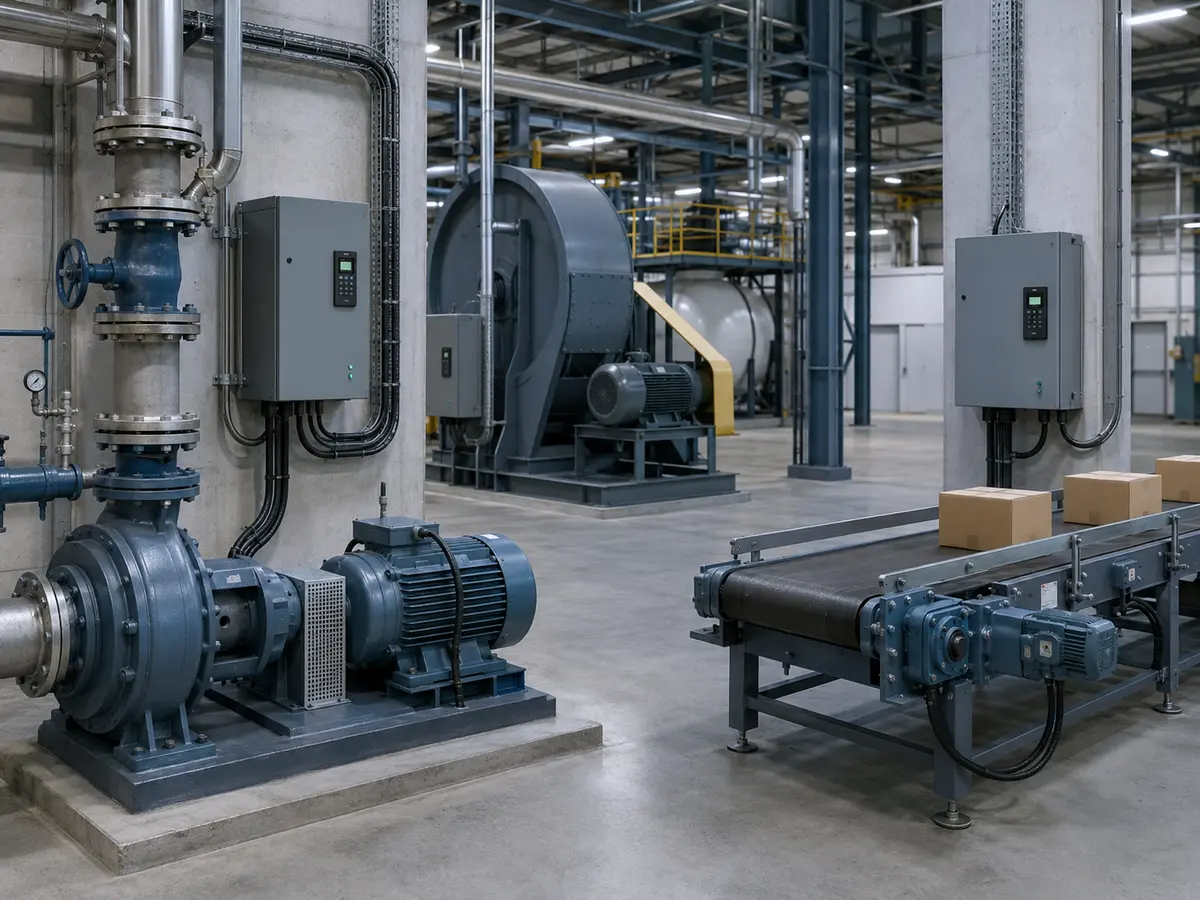
The table shows why “VFD application” is more useful than “VFD motor size” as a starting point. A 15 kW fan and a 15 kW loaded conveyor can call for different overload ratings and control behavior. A centrifugal pump normally presents variable-torque duty. A positive-displacement pump can behave much more like a constant-torque load. The connected machine changes the selection.
What can a VFD control besides speed?
Speed is the best-known function, but it is only the beginning. Even a modest industrial drive can coordinate several parts of a machine’s behavior. Available functions vary by model, so buyers should treat the list below as a discussion guide rather than a promise that every drive includes every feature.
- Acceleration and deceleration: ramp times can reduce abrupt mechanical shock, belt slip, pressure surges, and high starting current.
- Direction and speed references: commands may come from the keypad, terminals, preset speeds, analog signals, a PLC, or an industrial communication network.
- Torque and current limits: the drive can restrict motor output or respond when the machine reaches a programmed operating boundary.
- Process feedback: an internal PID controller can adjust speed from a pressure, flow, level, temperature, or other measured signal.
- Monitoring and alarms: the keypad or network can report values such as current, frequency, run time, temperature, status, and fault history.
- Application sequences: selected drives add pump, fan, textile, crane, winder, compressor, or multi-motor functions.
These features do not remove the need for a machine control and safety design. A standard run command is not a safety function. An electronic current limit is not always a substitute for mechanical torque protection. The required risk reduction, stop behavior, isolation, emergency controls, and functional safety must follow the machine design and applicable rules.
When should you use a VFD?
Use a VFD when the process needs variable speed, soft acceleration, pressure or flow control, or a signal from a PLC or sensor. It can also reduce energy use on pumps and fans that spend long periods below full demand.
A fixed-speed load may only need a starter. If the motor runs at full speed after a gentle start, a soft starter may be enough. For accurate positioning or fast motion control, a servo system is often the better fit.
VFD, direct starter, soft starter, or servo?
A VFD is not automatically the best motor controller. The useful choice depends on what the motor must do after it starts. A simple comparison helps clear up four products that buyers often group together.
| Controller | Best fit | Main distinction |
|---|---|---|
| Direct-on-line starter | Fixed-speed motor where the supply and machine accept full-voltage starting | Starts and stops the motor without continuous speed control |
| Star-delta or reduced-voltage starter | Selected fixed-speed loads that need lower starting current | Changes the starting condition, then runs at line frequency |
| Soft starter | Fixed-speed equipment that needs a gentler start or stop | Controls voltage during starting and stopping; it does not provide normal continuous reduced-speed operation |
| Variable frequency drive | AC motor loads needing adjustable speed, process control, or a controlled ramp | Varies output frequency and voltage during operation |
| Servo drive and servo motor | High-performance motion requiring accurate position, speed, or torque | Uses a matched motion system and feedback for dynamic precision |
A soft starter is often enough when a pump only needs a controlled run-up and slow stop before operating at full line speed. A VFD becomes useful when the pump must also hold pressure as demand changes. At the other end of the range, a general-purpose VFD may run a spindle or indexing mechanism, but a servo system is often the better answer when the process depends on fast, repeatable position control.
The benefits are real, but they depend on the load
The most visible benefit is process control. Operators can match speed to production, pressure, airflow, temperature, level, or another operating target. A controlled ramp can also reduce sudden mechanical stress and make the machine easier to start with a weak electrical supply, although the supply still needs enough capacity for the actual load.
Energy saving receives the most attention. It can be substantial on centrifugal pumps and fans that spend many hours below full demand. Slowing the impeller or fan can avoid wasting energy across a throttling valve or damper. The U.S. Department of Energy describes VFDs as solid-state motor controllers that meet varying process requirements by changing the frequency and voltage supplied to an AC motor. Its guidance on adjustable-speed drive part-load efficiency also shows why the whole motor-and-drive system should be judged across its operating range, not at one catalogue efficiency point.
The saving is not universal. A conveyor that moves the same tonnes per hour at nearly constant torque may use roughly the energy the process demands, even if the VFD improves startup. A machine that must run at full speed all day may gain control or maintenance benefits without a large reduction in electricity. Drive losses, motor efficiency at reduced speed, static head, duty cycle, and process output all belong in a credible estimate.
A VFD can also reduce certain maintenance problems by avoiding hard starts, abrupt pressure changes, or aggressive mechanical braking. Yet it can introduce new work: clean cooling paths, inspect fans and capacitors, review fault history, keep connections sound, and protect the electronics from contamination. Good maintenance changes shape; it does not disappear.
What a VFD does not solve
A VFD cannot create motor torque beyond the current, voltage, thermal, and mechanical capability of the drive system. It cannot correct a pump selected outside its useful curve, a gearbox with the wrong ratio, a blocked air path, a loose coupling, or a motor that is too small for the load. It may reveal those problems sooner because it reports current or faults, but the root cause remains elsewhere.
- Low-speed cooling: a self-cooled motor moves less air when its shaft slows. Continuous high torque at low speed may require forced ventilation, a larger motor, or a revised duty.
- Braking energy: a high-inertia load or rapid stop can return energy to the DC link. The system may need a braking unit and resistor, a regenerative drive, or a longer stop time.
- Power quality: the input rectifier draws harmonic current. The installation may need reactors, filters, a multi-pulse arrangement, or an active front end after a system study.
- Motor insulation and bearings: PWM switching and cable effects can stress insulation and contribute to bearing currents. Grounding, cable practice, filters, and motor suitability matter.
- Existing output devices: capacitors and some protection or switching devices cannot simply remain between the drive and motor. Check every downstream component for VFD service.
- Hazardous or critical service: fire pumps, lifts, cranes, safety systems, and explosive atmospheres require specific equipment, controls, approvals, and engineering beyond a standard drive.
The ABB technical guide to AC drive control illustrates the common rectifier, DC-link, and inverter structure. It also shows why “changing frequency” is a useful definition but not a complete engineering description. The control method and motor model determine how effectively a drive manages torque and speed.
A practical example: throttled fan control
The old arrangement
A production exhaust fan uses a standard induction motor. The motor runs directly from the supply at full speed. Operators adjust airflow with a damper because some processes need much less extraction than others. The fan still creates full-speed pressure while the damper throws away part of that pressure.
What the VFD changes
The drive takes over motor starting and speed control. A duct pressure signal or PLC command tells it how much airflow the process needs. Instead of holding the fan at 50 Hz and closing a damper, the control reduces frequency and fan speed during lower demand. Acceleration and deceleration settings soften the change between operating points.
What the VFD does not decide
The engineer still checks the fan curve, minimum ventilation, resonance zones, motor current, motor cooling, cable length, enclosure temperature, sensor location, and the safe response to a failed signal. The energy estimate must use the real duty profile. If the process needs full airflow almost all the time, the predicted saving will shrink.
This example shows the proper role of a VFD. It changes the electrical conditions so motor speed can follow demand. The designer still owns the mechanical system, process limits, and safety sequence. Good projects connect those decisions instead of treating the drive as a box added at the end.
What should a buyer check after learning the definition?
Start with the machine rather than the VFD catalogue. Note what the motor drives, the required speed range, how the load starts, whether it can regenerate during stopping, and how the operator or PLC will command it. Add a readable motor nameplate photo, the site supply, cable length, enclosure location, ambient temperature, altitude, and any sensor or communication requirement.
Then move from education to selection. Our guide on how to choose a VFD explains load type, full-load current, voltage, speed range, overload duty, braking, control mode, and derating in a practical order. That is where a general definition becomes a model-ready inquiry.
Do not hide unknowns. If the motor plate is unreadable or the machine duty has changed, say so. Measured running current, the old drive model, a cabinet photograph, an operating video, or the pump and fan curve can provide useful context. A supplier can ask a clear follow-up question. It cannot safely correct a confident but inaccurate input.
Turn the definition into a useful inquiry
Send the motor plate, load, supply, and control target
UFELE can review the basic voltage class, continuous current, duty type, control signals, installation conditions, and required drive functions before quotation. Final machine and safety approval remains with the responsible system designer.
Variable Frequency Drive FAQ
Short answers to common VFD questions
These answers explain the basic terms. Motor data, load duty, the drive manual, and site conditions still decide the final application.
What is the main purpose of a variable frequency drive?
Its main purpose is to control an AC motor by adjusting the frequency and voltage supplied to it. This allows variable speed and can also provide controlled acceleration, deceleration, torque response, process feedback, and motor monitoring.
Is a VFD the same as an inverter?
In many markets, people use “inverter” as a short name for a VFD. Technically, the inverter is the output power stage that converts DC-link power into controlled AC. The complete VFD also includes the input conversion, DC link, control electronics, and interface.
Can a VFD be used with any AC motor?
No. The motor type, voltage, current, insulation, cooling, speed range, load, cable length, and control method must suit VFD operation. Older motors, long cables, hazardous areas, and demanding low-speed duty may need extra review or mitigation.
Does a VFD reduce a motor’s electricity use?
It can when lower motor speed reduces the work required by the process. Centrifugal pumps and fans with variable demand often offer strong opportunities. A constant-demand machine running near full speed may gain control benefits without a large energy saving.
What is the difference between a VFD and a soft starter?
A soft starter controls motor voltage during starting and often stopping, then the motor normally runs at line frequency. A VFD changes output frequency and voltage during operation, so it can run the motor continuously at different speeds.
Can a VFD convert single-phase power to three-phase?
Some drive models accept single-phase input and provide a three-phase motor output, but the manufacturer must approve that input arrangement. Current, derating, motor voltage, supply protection, and model limits need to be checked before purchase.