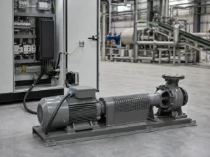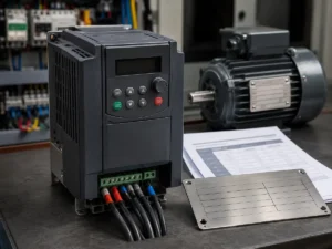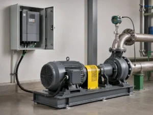
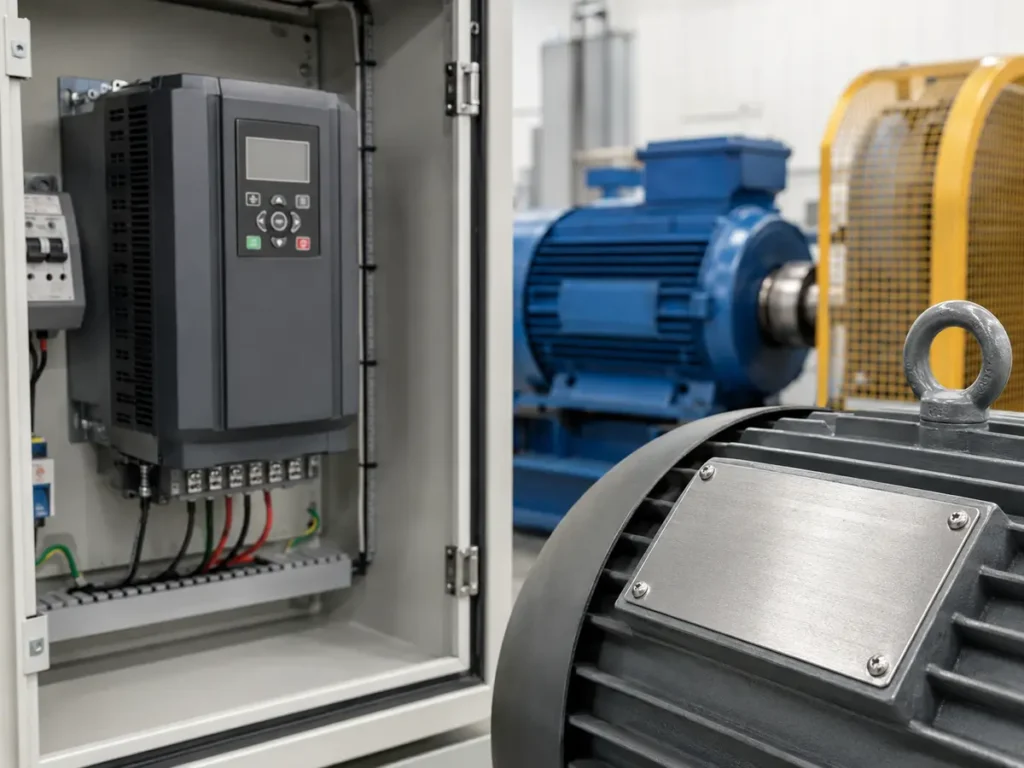
A motor plate is small, but it often carries the first facts that decide whether a VFD quotation is sensible. The uneasy part comes when one blurred photograph is expected to answer questions about voltage, current, connection, duty, and cooling that the plate never fully explains.
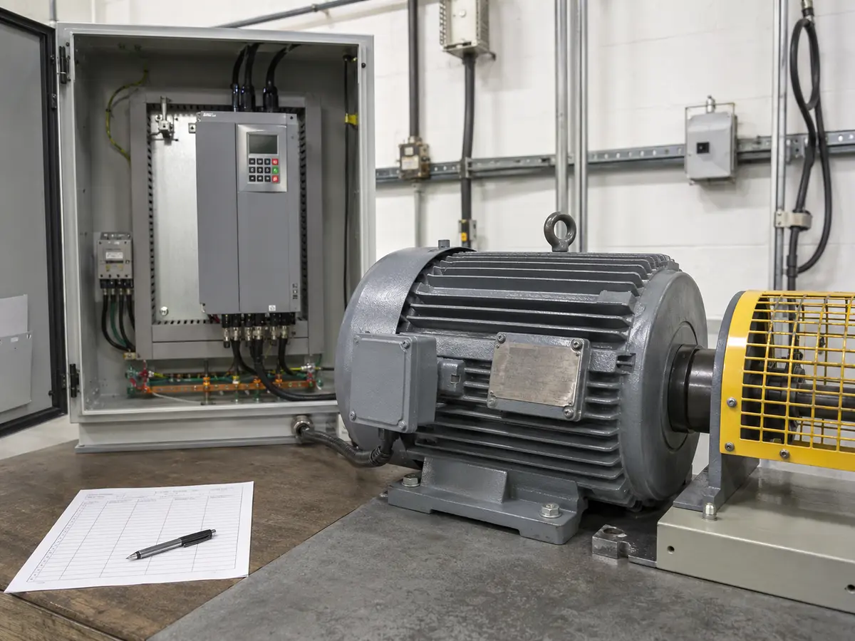 Read the complete plate and keep the connection diagram, supply voltage, and application notes beside it.
What should you read on a motor nameplate for VFD selection?
I first look for the figures that can stop a selection from going any further: phase, voltage and winding connection, followed by rated current and frequency. Power and speed help confirm that the photograph makes sense. Duty, cooling, insulation, enclosure, efficiency, and power factor fill in the thermal and operating picture. Even then, I compare the drive by output current and actual load duty. A matching kW label is reassuring, but it is not enough to approve the VFD.
A buyer may send a message that says “15 kW motor, need inverter.” It feels close to a quotation, but I would not choose a drive from that line. Two motors with the same kW can carry different rated currents, use different voltages, and face very different starting or low-speed demands. A clear plate photograph can prevent an expensive guess, although it is only the beginning of the conversation.
The awkward gap appears just after the plate has been read. We may now know the motor, yet we still do not know what is pulling on its shaft. A fan that starts gently, a loaded conveyor, and a hoist that must hold and stop a load can place very different demands on the same rated kW. Nor will the plate warn us that the motor spends most of its day turning slowly, with little air from its own fan. Our guide on how to choose a VFD deals with that side of the enquiry. The motor nameplate provides the electrical starting point, but load behaviour, speed range and site conditions still need a separate VFD review.
Before reading numbers, identify the motor and its condition
A familiar-looking motor can still make me pause. Three-phase induction motors account for much of ordinary industrial VFD work, so it is easy to assume that is what the photograph shows. The model and phase marking may tell a different story. Single-phase units, permanent-magnet or synchronous-reluctance motors, brake motors, high-speed spindles, and explosion-protected motors can change the drive, control method, or approval route. If the identity remains doubtful, I would mark it as unresolved and request the manufacturer reference. That small delay is much easier to defend than a confident selection built on the wrong motor type.
Ask whether the motor still has its original windings. A rewound unit may no longer behave exactly like the old plate suggests. Dirt, paint, corrosion, and a poor camera angle can also turn a 3 into an 8 or hide the delta symbol. When one character changes the voltage or current, I prefer another photograph taken square to the plate, plus a photo of the terminal links.
| Plate field | What it tells us | Why it affects the VFD review |
|---|---|---|
| Phase and motor type | Winding and control type | Confirms whether a standard three-phase induction-motor drive is appropriate |
| Voltage and connection | Rated winding arrangement at each supply voltage | Must agree with VFD output voltage and terminal links |
| Rated current | Motor current at rated conditions | Sets a central VFD output-current requirement |
| Power, frequency, speed | Rated mechanical output and operating point | Helps confirm the motor family, poles, base frequency, and speed plan |
| Duty, insulation, cooling | Thermal limits and how heat leaves the motor | Matters for overload, repeated cycles, carrier frequency, and low-speed operation |
Read voltage and connection as one statement
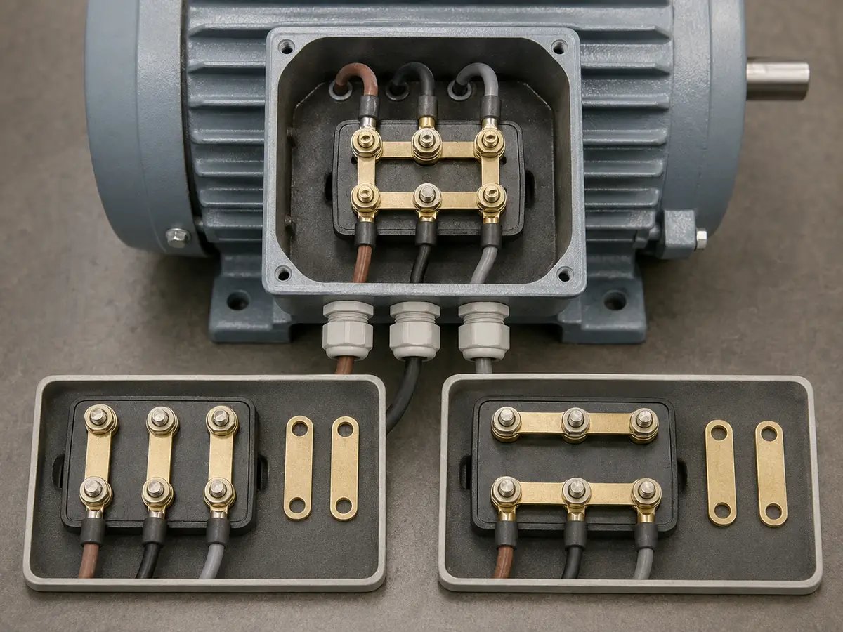
The slash between two voltages often causes more trouble than the faded print around it. With 230/400 V Δ/Y, the winding is normally arranged in delta for 230 V and star for 400 V; these are not two menu values to choose from later. On a 400/690 V Δ/Y plate, the usual pairing is 400 V delta and 690 V star. I want to see the terminal links because they show which of those conditions the motor is actually prepared for. They must agree with the voltage leaving the VFD, not merely with one number visible on the plate.
This is where a familiar kW size can lead the review astray. A 400 V-class drive cannot deliver 690 V merely because the motor plate includes that number. If a 400/690 V motor will run from a 400 V VFD, its normal full-voltage connection is usually delta, subject to the motor documentation and application. Leaving it in star may reduce the voltage across each winding and prevent the motor from producing the expected torque.
Also separate VFD input voltage from output voltage. A drive may accept one supply arrangement and create a controlled three-phase output, but it is not a general voltage transformer. Confirm the site supply, VFD input class, VFD output class, motor plate, and terminal connection on the same drawing. If a transformer or special boost topology is involved, write that into the project instead of hiding it behind a model code.
Use rated current to challenge a kW-only selection
Rated power on an IEC motor plate normally states mechanical shaft output. The electrical input is higher because the motor has losses. That is why dividing kW by voltage is not a reliable current calculation; phase, efficiency, and power factor all matter. The plate current gives us a much better starting point.
For a straightforward application, the VFD’s continuous output current must meet or exceed the motor rated current after any applicable derating. Heavy starting torque, shock load, rapid acceleration, high ambient temperature, altitude, a high carrier frequency, or a demanding duty cycle may require more current capacity. Pump and fan loads often behave differently from constant-torque conveyors or mixers, even when the motor plates show the same power.
I become cautious when a proposed drive matches the motor kW but its current rating sits just below the plate current. Choosing the next frame is not automatically the answer either; the drive’s motor-protection settings and control range must still suit the motor. Compare the exact drive model, normal-duty or heavy-duty rating, overload profile, and output-current table. The VFD power selection table is useful for an initial comparison, but the current and load decide whether that first match survives review.
Frequency and speed reveal the intended operating point
Speed is useful as a quiet cross-check on the frequency line. At 50 Hz, a reading around 1,470 r/min fits the behaviour expected from a four-pole induction motor running below its 1,500 r/min synchronous speed. Around 2,930 r/min suggests a two-pole design instead. I do not use that clue to overwrite a blurred plate. I use it as a reason to ask for a better photograph when the frequency, speed, and claimed motor do not seem to belong together.
Running a motor above base frequency needs a deliberate mechanical and torque review. The VFD may increase output frequency, but available voltage does not continue rising forever. Beyond the base-voltage point, the motor commonly enters a field-weakening region and available torque falls. Bearings, rotor balance, fan speed, driven-machine limits, noise, and critical speeds may become more important than the drive’s maximum frequency setting.
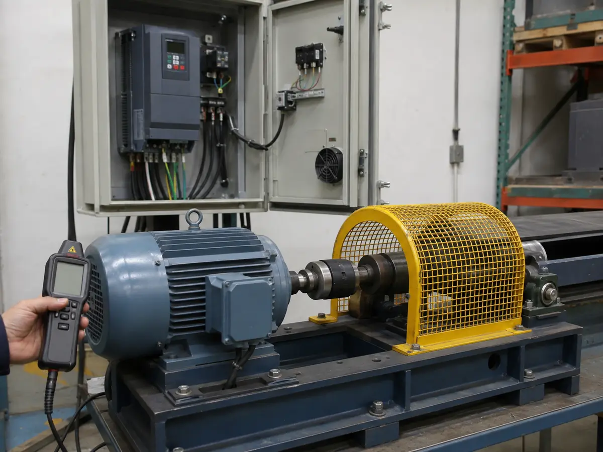
Low speed creates the opposite worry. A shaft-mounted fan turns slowly with the motor, so cooling weakens while a constant-torque load may still ask for substantial current. The motor can feel calm and quiet while heat builds inside. If the application must work slowly for long periods, ask for the minimum continuous speed, load torque, ambient temperature, and cooling method. A separately powered fan or a motor designed for inverter duty may be needed.
Duty and cooling explain how long the motor can carry the load
A marking such as S1 indicates continuous duty under the specified conditions. Other duty types cover short-time or intermittent operation with defined cycles. Do not assume an intermittent-duty motor can deliver its plate power continuously after a VFD is added. Obtain the duty description, starts per hour, loaded and unloaded times, acceleration time, braking sequence, and expected speed pattern.
The cooling code and enclosure deserve attention too. An enclosed fan-cooled motor behaves differently from an open motor or a unit with separately driven ventilation. IP rating addresses ingress protection; it does not promise that the motor will stay cool at every VFD speed. When the cabinet and motor sit in a hot, dusty plant, both thermal stories need to be believable.
Insulation class identifies the winding insulation system, but the simple letter does not settle inverter suitability. Fast VFD output pulses, reflected-wave voltage on long motor cables, high carrier frequency, and repeated thermal stress can challenge insulation and bearings. Ask the motor manufacturer about inverter duty, permitted cable length, winding voltage stress, and bearing protection when the installation is demanding.
Do not ignore efficiency, power factor, frame, and protection data
Efficiency and power factor help us understand why electrical input and shaft output differ. They are useful when checking an implausible current value, estimating system input, or comparing motors. They should not be used to invent a replacement plate current when the original value is available.
The frame size and mounting code help confirm shaft height, flange or foot arrangement, and mechanical interchangeability. They do not normally choose the VFD, yet they can reveal that a photograph belongs to another machine. Bearing data, weight, temperature-rise class, ambient limit, altitude, and certification markings may also appear. Record what matters to the destination market and the actual installation.
Brake motors need special care. The electromagnetic brake usually requires its own correctly timed supply and control; it should not simply follow variable VFD output unless the brake manufacturer designed it that way. Likewise, a motor thermistor or thermal switch should be identified, wired, and configured rather than left unused in the terminal box.
A 15 kW plate that still leaves work to do
Consider a plate photograph that is clear enough to read: three-phase induction motor, 15 kW, 400/690 V Δ/Y, 29.5/17.0 A, 50 Hz, 1,470 r/min, S1, IP55, insulation class F, and IE3 efficiency. The site note adds a 400 V three-phase supply and says the motor drives a loaded conveyor. This feels much better than a kW-only enquiry, but I would still resist turning it straight into a model number.
I would read the 400 V operating point together with the delta symbol and expect the terminal links to follow the motor maker’s 400 V delta diagram. The 29.5 A plate value then becomes the relevant rated-current reference, not 17.0 A. A VFD offered only because “15 kW” appears on its label still needs its continuous current, heavy-duty overload, ambient derating, and acceleration duty checked.
| Review point | Illustrative plate or project data | What remains to be confirmed |
|---|---|---|
| Supply and motor voltage | 400 V site; 400/690 V Δ/Y motor | 400 V-class VFD output and correct delta terminal links |
| Motor current | 29.5 A at 400 V delta | VFD continuous output current after duty and environmental derating |
| Load | Loaded conveyor | Starting torque, acceleration time, shock load, and overload profile |
| Speed plan | 1,470 r/min at 50 Hz | Minimum continuous speed, maximum speed, cooling, and mechanical limits |
| Installation | S1, IP55, class F | Ambient, altitude, cable length, switching frequency, and inverter-duty evidence |
The example is not a recommendation for a particular VFD frame. If the conveyor starts empty, the answer may be easier. If it restarts full, accelerates quickly, reverses, or cycles often, current and braking demands can change the result. A plate gives us firm data, but it cannot feel the load on the shaft.
When the nameplate is missing, damaged, or doubtful
Do not guess a hidden current digit from motor size alone. Ask for several photographs under side lighting, the full motor model, terminal-box diagram, existing starter or drive settings, machine documentation, and measured supply. If the original manufacturer can identify the serial number, its data is preferable to an estimate.
A clamp-meter reading can help diagnose an operating machine, but it does not automatically become rated current. The observed load may be light, unbalanced, or abnormal. Insulation tests, winding-resistance checks, and a competent motor inspection may be appropriate before connecting an old or unknown motor to a new drive.
When several motors share one VFD, or one motor changes between mains and VFD operation, the protection and switching arrangement needs a separate design review. Output contactors, individual overload protection, motor identification, and operating interlocks matter. This is no longer a one-plate, one-drive selection.
What to send with a VFD quotation request
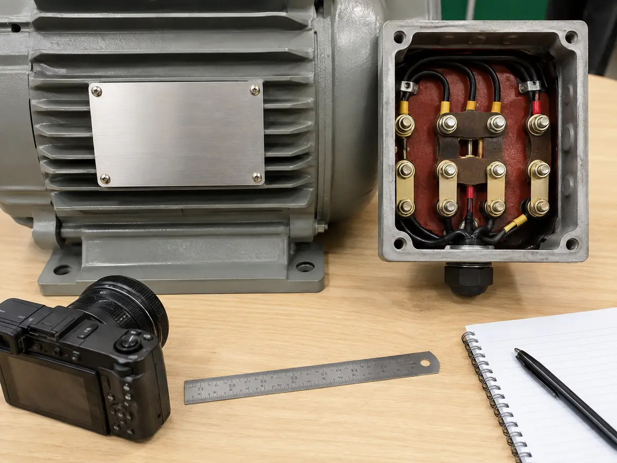
A useful quotation file begins with two photographs: one square to the complete motor plate and one showing the terminal links. Beside them, note the motor model and the site’s voltage and frequency. Then describe the machine in working terms. Is it normally loaded when it starts? How slowly and how quickly must it run? How much time is allowed for acceleration and stopping, and how often does that cycle repeat?
The installation details can follow without becoming a wall of unexplained data: ambient temperature, altitude, motor-cable length, enclosure conditions, braking duty, and required control signals. Call out anything that could otherwise be discovered too late, including an encoder, mechanical brake, thermistor, bypass, output contactor, reactor, or EMC requirement. A short note explaining why each item is present is more useful than a long checklist copied into an email.
If you are comparing quotations, keep every supplier on the same duty definition. One may quote normal duty while another uses heavy duty. One may include a braking unit, reactor, or keypad extension that another leaves out. Our guide to VFD parameters explains how to read those drive-side terms once the motor data is settled.
Motor nameplate and VFD review checklist
- Motor type, phase, model, and winding condition are known
- Rated voltage is matched with the correct star or delta connection
- Rated current is readable and used in the drive-current check
- Frequency, rated speed, and required speed range agree
- Load torque, starting condition, and overload profile are described
- Duty, cooling, insulation, IP rating, ambient, and altitude are reviewed
- Cable length, braking, motor sensors, and control requirements are recorded
- The exact VFD model and duty rating appear on the quotation
UFELE supplies variable frequency drives for pump, fan, conveyor, machinery, and other motor-control applications. Send the motor and load file through our contact page. We will point out missing information before turning a convenient kW match into a formal selection.
Frequently asked questions
Which motor nameplate value is most important for VFD sizing?
Rated current at the actual operating voltage and connection is a central value. It must be reviewed with motor power, load type, overload, duty, speed range, environment, and VFD derating rather than used alone.
Can I choose a VFD using only the motor kW?
No. The same kW can involve different currents, voltages, duties, and loads. Confirm the plate current and application before approving the drive.
What does 400/690 V Δ/Y mean on a motor plate?
It commonly means the winding is connected in delta for 400 V operation and star for 690 V operation. Follow the exact motor diagram and confirm the VFD output voltage.
Can a 50 Hz motor run above 50 Hz with a VFD?
Possibly, but the motor and machine need a torque, voltage, cooling, bearing, and mechanical-speed review. The VFD maximum frequency setting alone does not approve the higher speed.
Why can a motor overheat when a VFD runs it slowly?
A shaft-mounted cooling fan also slows down, while a constant-torque load may still demand substantial current. Long low-speed operation may require separate cooling or a suitable inverter-duty motor.
What if the motor nameplate cannot be read?
Request better photographs, motor and machine records, terminal details, and manufacturer data. Measurements can support an investigation, but they should not be casually treated as missing rated values.