A panel count can look convincing in a quotation and still be wrong at the first cold start or hot afternoon. When we review solar panel sizing for water pumps, one reassuring wattage total is never enough. We want to know how the string behaves while running, what its voltage becomes in the cold, how much current reaches the inverter, and how much of the stated array power the site can really use. That means opening the exact module sheet and inverter manual, not working from a familiar model name.
How do you size solar panels for a water pump?
We do not begin by counting modules. The pump still has to deliver the required water, and the chosen inverter still has to suit its motor. Only then does a string calculation mean anything. We check whether hot modules can keep the inverter working, then look at the same string on the coldest expected morning. If either result feels too close to a limit, we stop there rather than leave the installer to discover it. Parallel-string current and array power come next, with final approval tied to the manuals for the two exact models.
The uncomfortable part of this calculation is that one neat number will not settle it. A buyer may ask, “How many 550 W panels do I need for a 7.5 kW pump?” We understand the appeal of a quick answer. It helps with price, freight, and mounting space. Yet a module wattage tells us almost nothing about whether ten, twelve, or sixteen panels belong in one string.
The voltage class of the inverter changes the answer. So do the panel’s Vmp and Voc, the coldest morning at site, and the cell temperature under strong sun. Even two modules carrying the same 550 W label can produce a different safe string range. If we ignore those details to make the quotation move faster, the installer is the person left with a system that trips, refuses to wake up, or never reaches useful speed in hot weather.
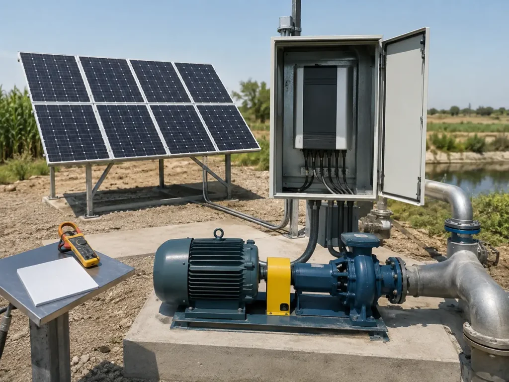
This article focuses on the array-to-inverter interface. The water source, pump curve, pipe loss, tank, sensors, and protection still matter; our guide to solar pumping system components explains how those parts connect. For the motor-side selection, see the separate solar pump inverter sizing guide.
Put three documents on the desk before calculating
A dependable calculation begins with the PV module data sheet, the solar pump inverter manual, and the site temperature record or design basis. The motor plate and pump duty should already have been checked. If any of these items is missing, mark the answer as preliminary. That small word matters. It prevents an early estimate from quietly becoming an approved purchase list.
A module sheet can be several pages long, yet the numbers we need are easy to miss when someone sends only a sales summary. We look for Vmp and Imp at the maximum-power point, Voc and Isc, rated power, power tolerance, and the voltage temperature coefficients. The maximum system voltage and series-fuse rating also earn a place in the file. I would not borrow these figures from the next model in the range. One suffix in a module code can change the calculation enough to make an earlier answer useless.
The inverter side often takes more patience. We need its start voltage, normal DC or MPPT window, absolute maximum DC voltage, current limits, permitted array power, and the conditions attached to those ratings. A brochure that says only “DC 250–800 V” leaves me uneasy. It does not tell the person checking the string whether 250 V starts the drive, keeps it tracking, or merely marks the edge of an allowed range. Until the manual makes that clear, the calculation is unfinished.
| Source | Record these values | Why they matter |
|---|---|---|
| Full PV module data sheet | Vmp, Imp, Voc, Isc, Pmax, power tolerance, and voltage temperature coefficients for the exact model | These figures let us see what one proposed string will do in heat and cold, rather than trusting its wattage label |
| Exact inverter manual | Start voltage, MPPT or working range, absolute DC limit, input-current limits, and permitted array power | This is where we find the limits that can stop an otherwise tidy panel schedule from working |
| Site data | Lowest expected ambient temperature, high operating temperature, solar resource, shading, altitude, and mounting | Moves the design away from laboratory values and toward field conditions |
| Pump and motor file | Duty point, motor voltage, current, frequency, kW, and expected operating hours | Confirms what the inverter and array are being asked to support |
Series raises voltage; parallel raises current
Modules connected in series form a string. Their voltages add while the string current remains close to the current of one module. Put ten modules with a Vmp of 41.8 V in series and the STC operating voltage is 418 V. Their Voc adds in the same way. The calculation is simple; deciding whether 418 V is useful requires the inverter manual and a temperature check.
Parallel strings behave differently. Their currents add while the voltage stays at the string level. Two identical strings, each with an Imp of 13.16 A, give 26.32 A at maximum power under STC assumptions. The inverter input, combiner, cable, isolator, and protection devices must all suit the finished arrangement.
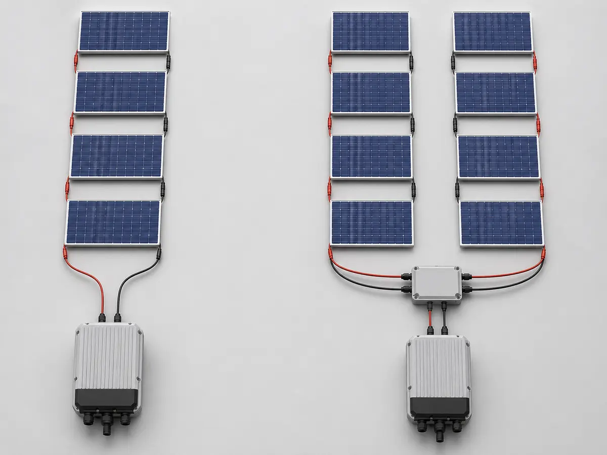
Keep parallel strings electrically consistent. A shorter string does not “help” a longer one; connecting unlike string voltages to the same input creates a mismatch. Module orientation, tilt, shading, and connector type also deserve attention. A design that is correct on paper can still lose badly when one row spends the morning behind a water tank.
Check whether hot-condition Vmp stays usable
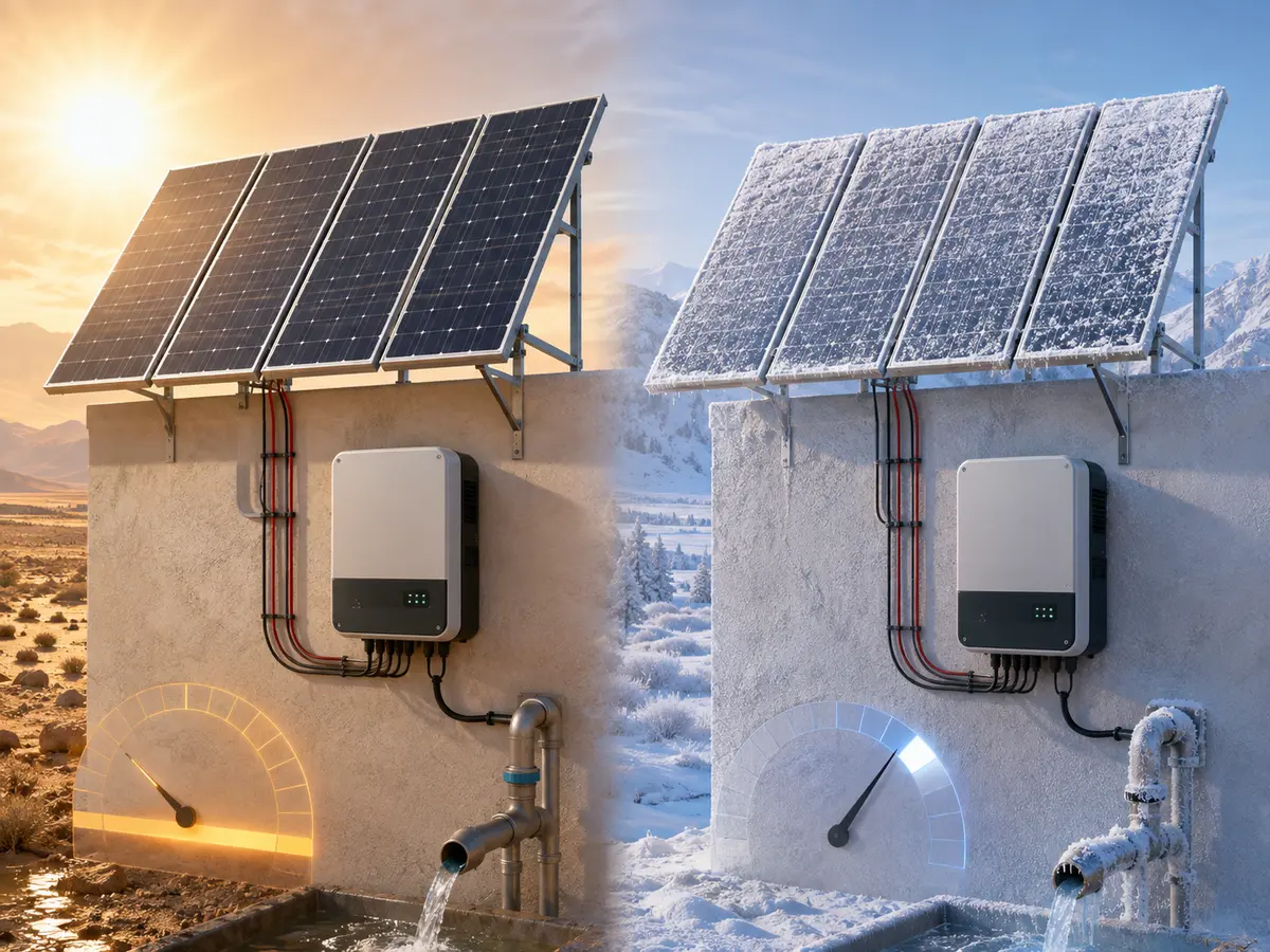
PV voltage falls as silicon cells become hotter. The U.S. Department of Energy notes that rising cell temperature causes a much larger drop in voltage than the accompanying increase in current in its overview of PV performance and temperature. This is why a string based only on its 25°C STC value can disappoint in the field.
Use the module manufacturer’s Vmp or Pmax temperature information and the design method required by the inverter supplier. A simplified Vmp correction, where the data sheet supplies a Vmp coefficient, can be expressed as:
Simplified hot-voltage check
Adjusted module Vmp = Vmp at STC × [1 + coefficient × (design cell temperature − 25°C)]
The coefficient must be entered in decimal form. For example, −0.29%/°C becomes −0.0029/°C. Use cell temperature when the method requires it; ambient air temperature is not the same thing. Module cells in strong sunlight often run much hotter than the air around them.
Multiply the adjusted module Vmp by the number of modules in series. The result should remain inside the applicable inverter operating range with sensible margin. We do not like seeing a hot-string result resting exactly on the lower boundary. Dirt, ageing, manufacturing tolerance, cable drop, and unusually severe site conditions do not care that the spreadsheet passed by one volt.
Check cold-condition Voc against the absolute limit
Cold weather moves voltage in the opposite direction. On a clear cold morning, an unloaded string can produce a higher open-circuit voltage than its STC rating. That figure must remain below the inverter’s absolute maximum DC input voltage. Crossing the limit is not a minor performance issue; it can damage the input stage and may fall outside the product warranty.
Use the module’s Voc temperature coefficient and the site’s lowest credible design temperature. A simplified check is:
Simplified cold-voltage check
Adjusted module Voc = Voc at STC × [1 + coefficient × (minimum design temperature − 25°C)]
Because the voltage coefficient is normally negative, a temperature below 25°C produces a higher corrected Voc. Multiply that value by the series count and compare it with the inverter’s absolute DC maximum. Follow the exact module and inverter instructions if they specify a different method or safety factor.
This is the check most likely to be forgotten when the project is being discussed in warm weather. A supplier sitting in Wenzhou in August may feel no cold at all, but the array could be heading to a high-altitude site that sees frost. The calculation belongs to the destination, not the weather outside the supplier’s office.
Confirm Imp, Isc, and the number of parallel strings
Voltage decides how many modules can sit in series. Current usually decides how many of those strings the inverter can accept in parallel. Compare the combined Imp with the permitted operating input current. Then check combined Isc against any short-circuit-current limit stated by the manufacturer. Do not assume those two inverter ratings mean the same thing.
Current calculations also influence the balance-of-system products. Cable ampacity, voltage drop, connector ratings, string fuses, a DC isolator, surge protection, and a PV combiner box must match the number of strings and the applicable design rules. The array layout should show polarity, conductor size, cable length, junction points, and the route into the inverter.
Array power is a design decision, not a kW-to-kW copy
Multiplying module quantity by rated watts gives the array’s STC nameplate power. It does not tell us how much power reaches the motor through every hour of the day. Irradiance, cell temperature, dust, shading, orientation, cable loss, inverter efficiency, motor efficiency, and the pump curve all stand between those two numbers.
A PV array may be larger than the motor’s kW rating, but the acceptable ratio comes from the inverter manufacturer and the water-yield design. Oversizing can extend useful pumping into weaker sunlight and offset field losses. It can also exceed permitted array power or input current if someone treats “more panels” as automatically safer. There is no responsible universal percentage that fits every model, climate, and duty.
The better question is whether the proposed array can support the required daily water volume in the critical season without violating any electrical limit. For a complete solar pumping system, the hydraulic demand and available solar window should shape the power decision together.
Worked example: 550 W modules on a solar pump inverter
Here is a made-up calculation that shows where a comfortable-looking string can begin to worry us. The module carries a 550 W rating at STC, with Vmp 41.8 V, Imp 13.16 A, Voc 49.8 V, and Isc 13.95 A. Its Vmp coefficient is −0.29%/°C and its Voc coefficient is −0.25%/°C. We will place ten modules in series, allow the cell temperature to reach 70°C, and test the other end of the design at −10°C. These numbers explain the method only; they do not approve ten modules for a real site.
| Check | Calculation | Illustrative result | Approval question |
|---|---|---|---|
| STC string Vmp | 10 × 41.8 V | 418 V | Where does this sit in the stated operating or MPPT range? |
| Hot module Vmp | 41.8 × [1 − 0.0029 × (70 − 25)] | About 36.34 V | Does the exact manual permit this temperature method? |
| Hot string Vmp | 10 × 36.34 V | About 363.4 V | Is it safely above the applicable lower operating boundary? |
| Cold module Voc | 49.8 × [1 − 0.0025 × (−10 − 25)] | About 54.16 V | Does the site design temperature and coefficient match the actual project? |
| Cold string Voc | 10 × 54.16 V | About 541.6 V | Is it below the inverter’s absolute DC maximum with required margin? |
| One-string Imp / Isc | 1 × module current | 13.16 A / 13.95 A | Are both current values within their relevant input limits? |
| Array nameplate power | 10 × 550 W | 5.50 kWp | Does the manufacturer permit this array power for the chosen inverter? |
The hot Vmp calculation is the moment many quick quotations become less comfortable. The string looked like 418 V at STC, then lost roughly 55 V under the assumed hot-cell condition. Whether 363.4 V is acceptable depends entirely on the exact drive. The cold Voc result poses a different question at the upper boundary. Both answers must pass before anyone celebrates the 5.50 kWp total.
If the project needs two parallel strings, the STC array becomes 11.00 kWp, combined Imp becomes 26.32 A, and combined Isc becomes 27.90 A. Recheck inverter current and power limits, cable size, combiner requirements, and protection. The second string changes far more than the number of panels on the purchase order.
Allow for the site the array will actually meet
Temperature is only one field condition. Partial shade can hold back a string even when the unshaded modules look perfect. Dust and infrequent cleaning reduce useful irradiance. Long DC cable runs add voltage loss. Poor orientation shortens the strong pumping window. Module mismatch, connector resistance, and ageing add smaller losses that become noticeable when the original design had no breathing room.
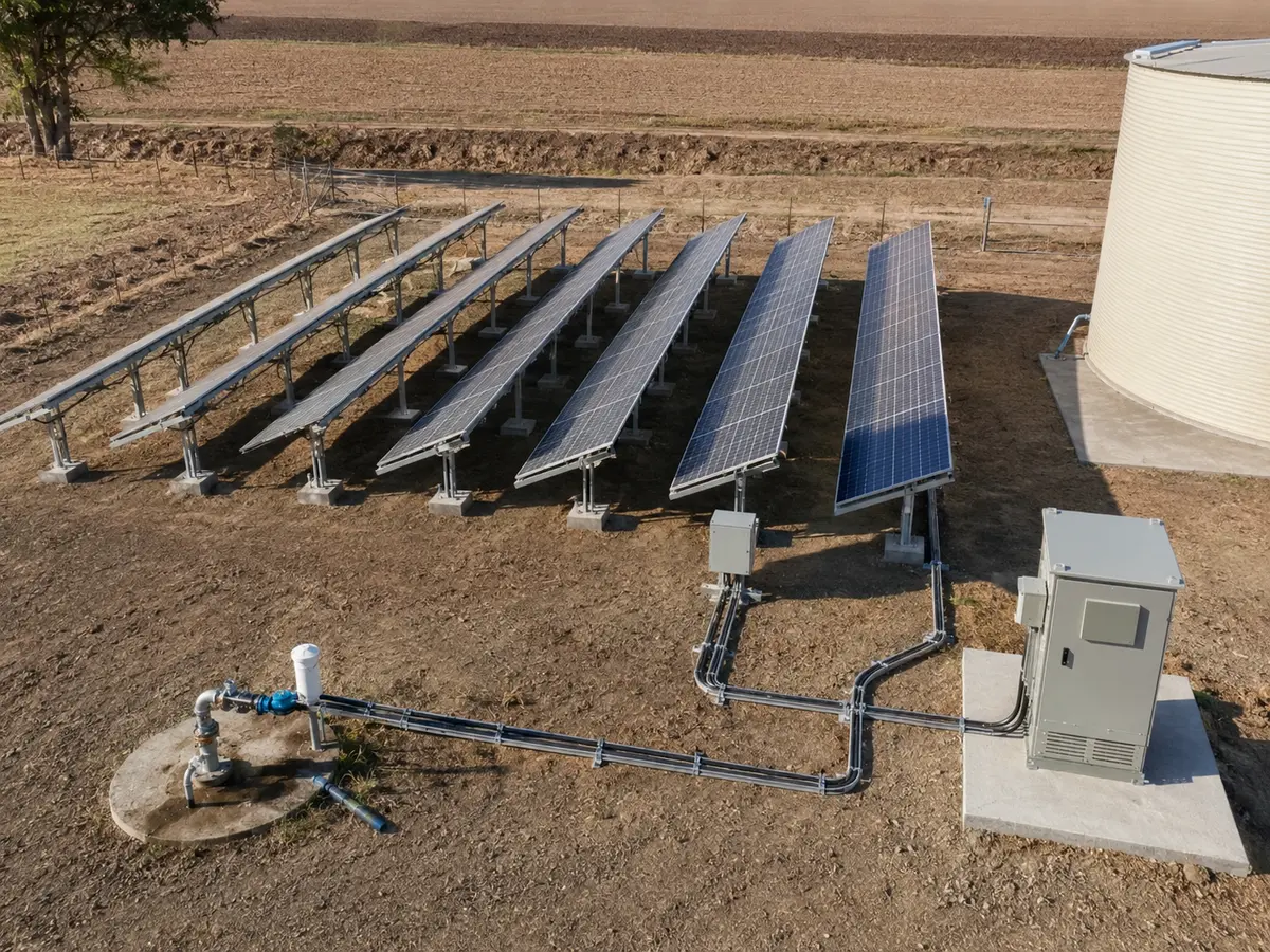
Mounting deserves its own line in the project file. Record tilt, azimuth, row spacing, foundation, wind conditions, corrosion exposure, cleaning access, and the source of any shade. A module plan should also show where strings begin and end. Installers should not have to reconstruct the designer’s intention from a pile of labels beside the borehole.
Altitude can affect the inverter and enclosure even though it does not change the module arithmetic in the same way as temperature. Check derating, cooling clearance, insulation requirements, and the expected temperature inside the cabinet. A PV calculation is not finished if the array is suitable but the drive has nowhere to release its heat.
What to include in the quotation file
Send the original module data sheet rather than a typed list of watts and volts. A clear label photograph helps confirm what was actually delivered. Include the full inverter model, motor plate, pump curve, project location, design temperatures, intended string layout, cable route, mounting drawing, and the required daily water duty.
Keep one revision-controlled calculation with the order. If procurement changes the panel model, repeat every affected voltage, current, power, connector, cable, and protection check. “Still 550 W” is not enough. We would rather pause a quotation for one reliable data sheet than ask an installer to solve an avoidable mismatch beside a full water tank or a silent pump.
Final PV array review
- Full module and inverter model codes are recorded
- Hot-condition string Vmp remains in the applicable working range
- Cold-condition string Voc remains below the absolute DC maximum
- Combined Imp and Isc meet the relevant inverter input limits
- Total array power complies with the exact inverter manual
- String layout, polarity, connectors, cables, isolation, and protection are documented
- Shading, temperature, altitude, mounting, cleaning, and cable length are included
UFELE supplies solar pump inverters and related solar energy equipment for project and distribution orders. Send the module sheet, motor plate, pump duty, and site data through the contact page. We can then identify missing information before the model and array arrangement are placed on the quotation.
Frequently asked questions
How many solar panels are needed for a water pump?
The quantity depends on the pump duty, motor and inverter ratings, module Vmp, Voc, Imp and Isc, local temperatures, solar resource, and permitted array power. Motor kW divided by module watts is not a complete sizing method.
Why must solar pump string voltage be checked in hot weather?
Module voltage falls as cell temperature rises. The temperature-adjusted string Vmp must remain inside the inverter’s applicable operating or MPPT range so the drive can run as intended during hot conditions.
Why does cold weather increase PV string risk?
Module open-circuit voltage normally rises as temperature falls. The corrected cold string Voc must stay below the inverter’s absolute maximum DC input voltage.
Can modules with the same wattage use the same string count?
Not necessarily. Modules with the same wattage can have different Vmp, Voc, Imp, Isc, and temperature coefficients. Recalculate the string when the full module model changes.
Can I oversize the PV array for a solar water pump?
Only within the exact inverter manufacturer’s permitted array-power and input-current limits. Oversizing may improve energy availability in weaker sunlight, but there is no universal safe ratio for every inverter, climate, and pump duty.
What PV panel details should I send for an inverter quotation?
Send the full module data sheet with Vmp, Imp, Voc, Isc, Pmax, temperature coefficients, and power tolerance. Also send the proposed series and parallel counts, site temperatures, project location, mounting plan, cable length, motor plate, and pump duty.